First-Hand:The World's First Transistor Hi-Fi System
Introduction
Submitted by Sorab K. Ghandhi with co-contributions by Vernon Mathis, Edward Keonjian and Richard Shea, whom are all now deceased.
The World's First Transistor Hi-Fi System
The first Solid State Circuits Conference, established by the AIEE-IRE, was hosted by the University of Pennsylvania in Philadelphia, PA in 1955. The meeting was held in the Irvine Auditorium of this University. Here, a late-news presentation was made on "Transistor High Fidelity Audio Systems", by Richard F. Shea of the General Electric Company (GE), Syracuse NY. It elicited a lot of excitement and anticipation since the transistor was known to be an extremely low power device, confined to hearing aids until this time.
At the presentation, Dick took the floor, where the amplifier was displayed in a small aluminum minibox. In addition, there was a turntable with a long playing (LP) phonograph record. This combination was incongruously placed on top of a large cabinet having a bare loudspeaker with a 12" cone and a bass-reflex port.
At the end of the talk, Dick asked the audience to be silent, turned on the amplifier, and placed the needle on the record. To everyone's amazement, the music blared out, and filled the entire auditorium. After a few seconds, a round of thunderous applause broke out from the stunned audience, and the age of the Solid State Hi-Fi Audio System was born. How this came about now follows.
The transistor was announced to the public by Bell Labs in 1948, and many companies started work on this device. One of these was GE, which had established an Electronics Laboratory in Syracuse, NY. I joined this organization in 1951, after obtaining my Ph.D. from the University of Illinois, and was assigned to work on this device under the direction of Richard F. Shea. Until that time, transistors were limited to low frequency, low power applications such as hearing aids. Coincidentally, Dick was hearing-impaired, so our entire group was set to work on his hearing aid. This was the World's First Transistor Hearing Aid, but that is another story.
At that time, GE had developed the Alloy Junction Transistor which was physically larger than the Bell Labs design, and announced a family of hermetically sealed devices with a power dissipation of 150 mW in free air, and over 300 mW when clamped to a heat sink. Dick decided that we should build a Power Audio Amplifier system using this device. Vernon Mathis and I were assigned to this task, since we were both interested in classical music, were hi-fi fans, and had made early vacuum tube phonograph systems for use with LPs in our home. Additionally, Edward Keonjian provided expertise in the low noise properties of the input amplifier stage.
At the outset, we recognized that we were dealing with a power amplification process from beginning to end. It was decided to operate all devices in the common emitter configuration, since the maximum transistor power gain is approximately equal to the square of its short circuit current gain. The system logically broke down into a Preamplifier and a Power amplifier. An additional stage was connected between these to make up for loss in the volume control circuit.
We designed our system for use with Long Playing (LP) records, which had replaced the 78 rpm record, because of their fidelity, and the ability to provide 30 minutes of playing time per side. However, their grooves were very closely spaced, so that the output from any transducer used with them required electronic amplification, even with vacuum-tube systems.
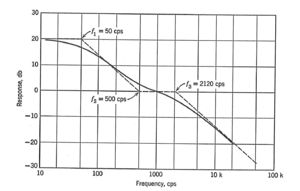
LP records were cut with pre-emphasis to preserve their response at high frequencies. The standard for this was set by the Recording Industry Association of America (RIAA). In order to compensate for this pre-emphasis, it was necessary to tailor the playback characteristic of the amplifier, as shown in Fig. 1. using the historical notation of cycles per second (cps). Here, the response was required to be flat from 500 Hz to 2120 Hz; falling at 20db/decade beyond 2100 Hz; rising at 20db/decade below 500 Hz, and eventually becoming flat below 50Hz. We chose to make this compensation at the front end, to minimize the operational dynamic range for the transistors.
LP systems typically used piezoelectric transducers which were ideally suited for operating with a high impedance load, i.e., into a vacuum tube amplifier. Recently, however, GE had developed the Variable Reluctance (VR) transducer with superior frequency response which had a very low mass (1 gm) and a diamond stylus. It had a much lower output voltage than the piezo units, about 50 mV at 1 kHz, necessitating a pre-amplifier when used with vacuum tube systems. However, it was a low impedance device, and was ideally suited for use with low impedance transistor circuits.
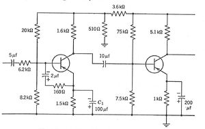
The VR transducer consisted of a low-mass coil in a magnetic field, and had an inductive source impedance. When terminated in a 6800 ohm load, its frequency response fell off at 2120 Hz. Thus, the high frequency compensation to the RIAA characteristic was readily met by designing the amplifier with an input impedance to 6800 ohms. The rest of the compensation (below 500 Hz.) was provided by an RC network between the emitter and the base. The preamplifier, complete with compensation for the RIAA characteristic, is shown in Fig. 2.
Special attention was paid to the input stage of this amplifier. We knew, from experience, that all transistors are prone to low frequency noise, referred to as 1/f noise, which increases inversely (at 3db/octave) above some critical frequency (500-1000 kHz). Extensive measurements at GE indicated that this critical frequency, and hence the transistor 1/f noise, was lowest in devices with the lowest collector reverse leakage current The input transistor was selected on this basis in order to minimize its noise, and operated at a reduced voltage by means of a resistive divider. All other transistors were randomly selected.
At this time, GE made a line of hermetically sealed alloy-junction germanium transistors, which were sorted according to their current gain into three types, the 2N43, 2N44 and 2N45. The 2N43 had the highest common-emitter gain (49), and was used throughout the amplifier. We had developed advanced bias stabilization techniques so that all transistors could be used with junction temperatures as high as 75 deg. C, without individual adjustment of their operating points. Note that this was in the pre-silicon transistor days.
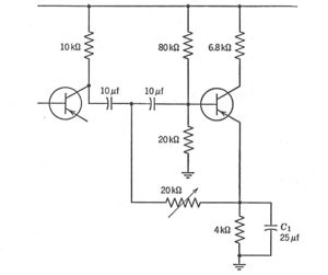
Both volume and tone control circuits were also developed during the course of our efforts, but the tone control circuits were omitted for this simple system. The volume control circuit is shown in Fig. 3 and required an additional transistor stage following the pre-amplifier of Fig. 2. Its output was transformer-coupled to the power amplifier, which drove the loudspeaker, also by transformer coupling. This limited the power supply to 25 volts for a 100% swing of the load line, since the 2N43 was rated conservatively for operation at a collector voltage of 50 volts. We used an available power supply of 28 volts, since the load-line swing was much lower (about 75%) in order to minimize distortion.
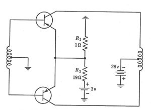
The power amplifier used two 2N43 transistors in a push-pull configuration in order to eliminate even-order distortion, and to increase the power output over that of a single device. Class B operation was used because it has significant advantages over a Class A system. Typically, the theoretical maximum power output of a push-pull Class A system is equal to 0.5 times the transistor power dissipation, while that of a Class B system is 3.68 times this dissipation. Additionally, the supply power is conserved because there is no steady state power dissipation under quiescent conditions.
Using two 2N43 transistors, each clamped to separate heat sinks, and a transformer efficiency of 80%, resulted in a theoretical maximum output power of 1.76 watts for a junction temperature of 75 deg. C. for the Class B amplifier. Finally, transistor power dissipation as well as power output are directly proportional to the square of the fractional swing of the load line over its I-V range. We calculated that a 75% maximum swing would result in an output power of 1 watt. Our output stage was designed for this fractional swing, to minimize distortion. This resulted in a maximum collector inverse voltage of about 41 volts, well within the 50V device rating.
A single disadvantage of Class B over Class A operation is the need to pre-bias these stages to prevent low level clipping. Typically, this pre-bias is about 0.1-.2 volts for germanium transistors. We developed a number of circuits to do this, eventually settling for the brute force approach of using a separate 3V battery for this purpose. Fig. 4 shows this amplifier, which was transformer coupled to the volume control circuit, and also to the loudspeaker load. It had an electrical output power of 1 Watt.
The choice of music selection and of the loudspeaker was critical for our demonstration. Dick wanted Harry Belafonte, but Vern and I insisted on the Bach Suite No. 2, because of its brilliant, loud opening, complete with trumpets and other wind instruments. After hearing it, Dick was impressed, and agreed.
Dick also wanted the system to be operated from a modest 5" loudspeaker because of its low power output. Fortunately, both Vern and I were familiar with the large Altec Lansing studio monitor speaker Model 601, with a 12" cone in a bass-reflex enclosure, which had excellent fidelity. More important, it had the highest electro-conversion efficiency of any speaker on the market at that time. It cost $100-200 in its enclosure, which was an intimidating price at that time. However, Dick bowed once more to our pressure and this is the unit we used for our demonstration.
The entire system consisted of five 2N43 germanium transistors, with two consigned to the Class B, push-pull output stage.
Conclusion
This report has outlined the design and implementation of the world's first transistor high fidelity amplifier system, designed for use with Long Playing phonograph records. The achievement here is that the entire system was designed, and not "slapped together". The design was considered as a power amplifier system from input to output, with transistors used in the common-emitter configuration to maximize power transfer. A moving coil transducer provided an excellent match to the low impedance characteristic of the input transistor. Robust bias stabilization design principles were used for all stages, allowing interchangeability of transistors. Compensation networks were designed for the RIAA recording characteristic, and implemented at the input end to avoid distortion in the amplifier stages.
Finally, a Class B output stage was used to maximize the power output during loud passages, while minimizing the power dissipation during soft passages. An additional advantage of push-pull operation was the elimination of even-order harmonic distortion in the system. Finally, a small pre-bias was applied to the output stage, to prevent crossover distortion.
References
Transistor Circuit Engineering. R.F. Shea, Ed. John Wiley and Sons, Inc. 1957.
About the Author
The author is an Emeritus Professor of Electrophysics, Rensselaer Polytechnic Institute, Troy NY. He and his wife Cecille share a love for Western classical music and for Mesoamerican archeology. They reside in Escondido, California USA.


