Electromagnetic Teleclinometer
The original version of this article was created by Francesco Gerali, 2019 Elizabeth & Emerson Pugh Scholar in Residence at the IEEE History Center
It is recommended this article be cited as:
F. Gerali (2019). Electromagnetic Teleclinometer, Engineering and Technology History Wiki. [Online] Available: https://ethw.org/Electromagnetic_Teleclinometer
Introduced in 1932, just 4 years after the establishment of electrical logging[1] in the petroleum fields of Europe, Caucasus and North America, the electromagnetic teleclinometer was conceived to determine the angle of inclination of the axis of a drill hole in relation to the vertical and the azimuth (of this inclination) and referring to the magnetic North. The electromagnetic teleclinometer was able to give the angle and the azimuth of the inclination simultaneously. These parameters over a series of increasing depths, 20-30 meters (65 to 98 feet) for example, allowed for easy calculation of the deviation graph as long as the hole is approximately straight between the consecutive measuring points, a condition which is quite sufficiently realized in practice with the measuring points close together.
The increasing of the rapidity (pace of drilling) of the execution of the borehole, in particular with the diffusion of the rotary drilling systems, were often the cause of considerable deviation from the original calculated vertical - the inclination of the holes sometimes could be greater than 20 degrees. The result in the deep wells was the bottom of a drill hole was to be situated several hundred meters from the vertical of the location. For many practical applications it was very important to know the exact deviation angle at different depths, and being able to plot a graph giving (in horizontal projection, for example), the curve followed by the drill hole in the ground.
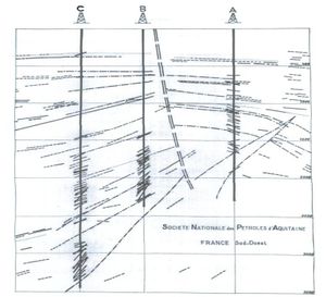
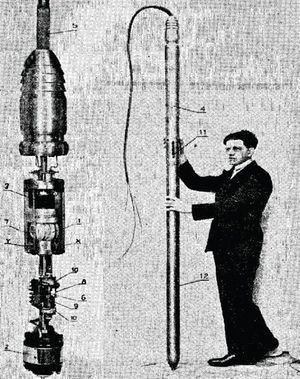
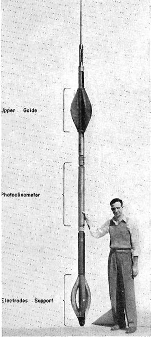
The functioning of the electromagnetic teleclinometer is based on the use of an induction compass moved by an electric motor and of an electromagnet supported by a cardan suspension[2] whose magnetic field influences the coil of the compass in proportion to the inclination. The apparatus, whose diameter was 10 cm. (3.9 inch), comprised of three insulated conductors, was lowered into the well bore by means of a cable, and the measurements were recorded at the surface with a potentiometer.[3] The measurements were extremely rapid, lasting less than a minute at each point, so that 1000 meters (3280 feet) of drill hole could be surveyed in about an hour. The measurements were accurate to within half a degree. The dipmeter[4] was an improvement on the teleclinometer, which was built by adding to the latter an extension comprising a pole for sending current into the ground, and measuring electrodes. It did permit the measurement of the equipotential surfaces induced by the passage of the current, from which can be deduced the direction of the dip of the beds in relation to the magnetic North.
The apparatus employed in the early 1930s was a pretty expensive instrument, very delicate and therefore the logging (measurements) and recording had to be made with precautions sometimes difficult to secure in the proximity of the rig.
See also
References
Doll, H. G. “The S. P. Dipmeter”. American Institute of Mining and Metallurgical Engineers. Technical Publication No. 1547. (Class G, Petroleum Division, No. 180; Class L, Geophysics, No. 93 (1942): 1-10.
Johnson, Hamilton M. “A History of Well Logging”. Geophysics XXVII, no 4 (1962): 507-527.
Schlumberger, C., Schlumberger, M., & Doll, H. G. “The Electromagnetic Teleclinometer and Dipmeter”. Proceedings of the 1st World Petroleum Congress, 18-24 July, London, UK (1933): 424-430.


