Resistor
The resistor is a fundamental electrical component in physical circuits as well as circuit analysis and equivalent circuits. It was the earliest electrical attribute - identified shortly after electrical current was discovered. All materials exhibit some form of resistance, some are greater than others, eg. copper, aluminium and gold are considered good conductors (low resistance), stainless steel, carbon, tungsten are average conductors (medium resistance), and then ceramics, mica and air are considered poor conductors (high resistance).
Ohms Law defines the relationship between circuit attributes:
- Resistance = Volts / Current
- Resistance = Power / ( Current^2 )
A non ohmic attribute of Resistance can also be defined as a function of noise voltage, as part of Noise Power = kTBf, where is resistor that is above absolute zero temperature is a source of noise.
When a resistor is combined with either a capacitor or inductor, the current through this network will be out of phase with the applied voltage, and described as dispacement current. The combination of resistance with capacitance / inductance is is known as impedance, and complex mathematics is used to build on the basic ohms law shown above.
Units of Measurement
The modern day unit of measurement is the 'Ohm'. This unit was assigned in 1872. The measurement standards for the Ohm reference has improved over time, and these standards are maintained by NIST / NATA standards laboratories in temperature controlled environments.
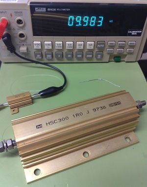
Given the wide range of resistance values and related measurements, the value of resistance is often prefixed with the the greek multiplier terms, eg. nano-ohm, kilo-ohm, meg-ohm. Resistors are also specified with a power handling capacity, in watts, eg. half-watt, 50 watt, 10kilo-watt etc.
The unit of measurement for the inverse of Ohm (ie 1/R) is known as the 'Siemen', often used in very low value resistance measurements. In earlier times this unit was known as Mho, and often used to characterize vacuum tubes.
Color Coding
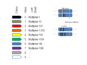
Traditional wire leaded resistors are typically color coded to show their resistance value and manufactured tolerance. There are 3 or possibly 4 color coding bands, with examples of their values shown in the diagram in the right. The power ratings are not generally specified on the device, but is usually a function of the physical size of the resistor.

