First-Hand:My Personal History With APS, Part 2b
My Personal History With APS, Part 2b
By William F. Croswell, Life Fellow. This article is a contination of Part 2A.
Introduction
During the early 1960’s, when my colleagues and I were concentrating on the impedance of antenna apertures located on flat and curved ground planes covered by lossy and inhomogeneous media, I was also concerned with the patterns of antennas mounted on aircraft. After obtaining some grant money from NASA Headquarters, I went to the University of Michigan Radiation Laboratory and spoke with Ralph Hiatt, the lab director and Tom Senior, a member of the lab and a professor of the university. The Radiation Lab was well known for work on radar cross-sections and scattering. After a year or so the Radiation Lab staff made little progress on the aircraft antenna problem. I made trips to Ann Arbor every 3 or 4 months and became convinced that no progress at the end of a year or so was being made.
At this point, I decided to go to the Ohio State University and had a long discussion with Dr. Roger Rudduck. Roger over the next few years was able to solve a number of antenna patterm problems using wedge diffraction analysis, and the solutions were very useful in entry physics problems. Roger wrote over 20 reports as referenced in part IIa of this history. However, this work was not useful for aircraft antenna pattern analysis.
During a visit to the OSU Electroscience Laboratory, I had a meeting with Professor Bob Kouyoumjian and his new PhD student Prabakar Pathak. They were trying to develop the Geometrical Theory of Diffraction including canonical problems that could apply to aircraft antenna problems. Based upon their early work[1][2][3][4][5], Professor Kouyoumjian started teaching GTD methodology in his classes where his students, Dennie Burnside and Ron Marhefka started applying the GTD techniques to the aircraft antenna problem.
Aircraft Models
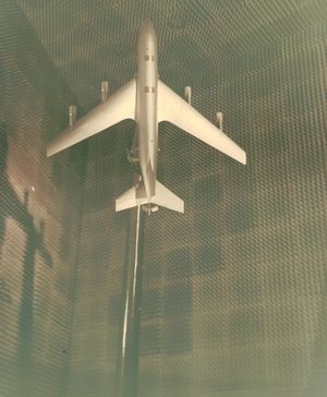
At the beginning of the 1960’s the building 1299 was built at NASA Langley and I was project engineer. I decided to build two antenna chambers which, at the time were the two largest in the country. One was 90’x30’x30’ and operated at 200 MHz, and the other was a tapered horn chamber of similar length with a 30’x30’ aperture and operated down to S Band. The tapered chamber was ideal for measuring the patterns of antennas mounted on scale model aircraft .The aeronautical engineers at NASA Langley were able to develop detailed drawings for aircraft. These scale models could be made in great precision by the model shop that built aircraft models for wind tunnel tests. I asked Mel Gilreath, who worked for me, to be responsible for the scale model aircraft and to coordinate the work ultimately with the staff at the OSU Antenna Laboratory. Mel was an extremely thorough person. The first scale model airplane Mel built was a 1/25th scale model KC -135, as shown in Figure 1.
Development of GTD Methods of Predicting Antenna Patterns on Aircraft Scale Models
Denny Burnside and other OSU Electroscience staff developed theoretical methods using GTD to predict the patterns of antennas on scale model aircraft. The scale model aircraft and measurements were developed by Mel Gilreath.
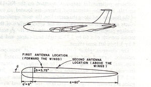
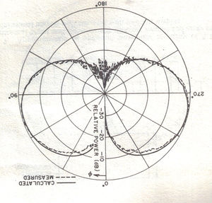
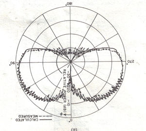
The theoretical model of the fuselage is shown in Figure 2. The wings and tail structure were modeled with flat plates as shown in Figure 3. Details of the ray analysis are given in detail[6]. The analysis developed[6] produces results that are accurate in the roll plane as shown in Figures 3 and 4.
The analysis which was used to compute the patterns in Figures 4 and 5 will not allow computation of the elevation patterns and the inclusion of the tail structure and other pieces of aircraft structure. The inclusion of such structures to compute volumetric antenna patterns is given in the references[7][8]
Thin Wire Structures and the Moment Method
During a visit to the OSU Electroscience Laboratory I stopped by to see Dr. Jack Richmond. Jack told me he was losing research support because he could not get his papers published in the Transactions on Antennas and Propagation. Upon returning home I was able to obtain research and grant funding for what became known as the Method of Moments. I called Jack and told him I would publish his papers as NASA Contractor reports. These reports are listed in the references.[9][10]
Several years later, I became Editor of the AP Transactions. I inherited the files from the previous editor, Leon Ricardi. In those files I found papers by Jack Richmond and Roger Harrington in the rejection file. I met with Dr. R.W.P.King at the APS meeting and discussed with him his reasons for rejecting the papers by Richmond and Harrington. Dr. King basically stated that his integral equation method was the only proper way to solve such problems with dipoles. I pointed out that the analyses Richmond and Harrington proposed were very straightforward to implement in order to compute antenna properties of wire antennas mounted on aircraft and missiles. In addition, there were now numerous cases of excellent agreement between MOM and wire antenna theory and experimental data.
For the continuation and conclusion, see part 3.
References
- ↑ Koumoumjian, R.G. and Pathak, P.H.,”A Uniform Geometrical Theory of Diffraction for a Edge in a Perfectly Conducting Surface“ Proceedings of the IEEE, vol. 62, pp. 1448-1461, November, 1974.
- ↑ Kouyoumjian, R.G. and Pathak, P.H., “The Dyadic Diffraction Coefficient For a Curved Edge”, NASA CR -2401, June, 1974.
- ↑ Kouyoumjian, R.G. and Pathak,P.H., ”An Analysis of the Radiation from Apertures in Curved Surfaces by the Geometrical Theory of Diffraction“, Proceedings of the IEEE, vol. 62, pp. 1438-1447, November, 1974.
- ↑ Pathak, P.H., ”An Asymptotic Analysis of the Scattering of Plane Waves by a Smooth Convex Cylinder”, Radio Science, May-June, 1979.
- ↑ Pathak,P.H., Burnside, W.D., and Marhefka, R.J.,” A Uniform GTD Analysis of the Diffraction of Electromagnetic Waves by a Smooth Convex Surface”, IEEE Transactions on Antennas and Propagation, vol. 28, pp. 631-642, September,1980.
- ↑ Jump up to: 6.0 6.1 Burnside, W.D., Gilreath, Melvin C., Marhefka, Ronald,J., Yu,Chong L.,”A Study of KC-135 Aircraft Antenna Patterns”, IEEE Transactions on Antennas and Propagation, vol. 23, pp. 309-316, May,1975.
- ↑ Yu, C.L., Burnside, W.D., and Gilreath, M.C., “Volumetric Pattern Analysis of Airborne Antennas”, IEEE Transactions on Antennas and Propagation, vol. 26, pp. 636-641, Sept., 1978.
- ↑ Richmond, J.H., ”Radiation and Scattering by Thin-Wire Structures in the Complex Frequency Domain”, NASA Contractor Report-2396, May,1974.
- ↑ Richmond, J.H., and Wang,N.,”Sinusoidal Reaction Formulation for Radiation and Scattering from Conducting Surfaces“, NASA Contractor Report-2398, June, 1974.
- ↑ Richmond, J. H.,”Computer Program for Thin Wire Structures in a Homogeneous Conducting Medium”, NASA Contractor Report-2399, June, 1974.
