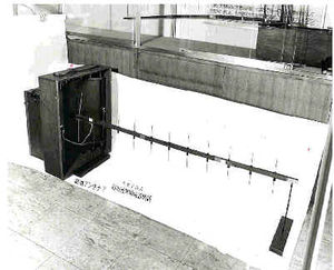
Milestones:Directive Short Wave Antenna, 1924
Directive Short Wave Antenna, 1924
Miyagi, Japan Dedicated June 1995 - IEEE Tokyo Section
In these laboratories, beginning in 1924, Professor Hidetsugu Yagi and his assistant, Shintaro Uda, designed and constructed a sensitive and highly-directional antenna using closely-coupled parasitic elements. The antenna, which is effective in the higher-frequency ranges, has been important for radar, television, and amateur radio.
The plaque can be viewed at Tohoku University, outside near the statue of Dr. H. Yagi; Aoba-cho, Sendai-shi, Miyagi-ken, 980, Japan. For photographs of the ceremony, please click here.
The antenna system, using a driven element with closely coupled parasitics (usually a reflector and one or more directors) for short-wave work, was first described by S. Uda, a lecturer at Tohoku Imperial University in Japan, in 1925, in the Journal of the IEEJ (Japan). The director of short-wave research into communication methods using electricity, Professor H. Yagi, guided the developmental work and published the more widely read English version in the June 1928 IRE Proceedings. The antenna, sometimes termed a Yagi, should be credited to both inventors.
The invention came at a crucial time in the development of short-wave engineering when new tubes permitted higher frequency and more stable outputs. Applications such as amateur radio, point-to-point communication, VHF Radar and television receiving were natural outlets for the Yagi-Uda antenna system.
In the basic technical operation a driven element, usually ½ l is connected to the transmitter through coax cable. In close proximity to the driver, but not physically connected to it is a reflector, usually more than ½ l and one or more directors (usually less than ½ l ). The E.M. wave interaction between the elements of the "beam" antenna acts to re-radiate the signal in a specific direction (i.e. in the direction of the "directors") and with a significant "power gain" - a good beam figure is in the area of 7 db. gain.
In reception the reverse occurs, and a weak signal is acted upon by the director network to boost the signal up to 7 db.
The Yagi-Uda antenna has a narrow frequency range as a consequence of its ability to provide power gain in a specific direction. Also there is a power limitation which prevents many kilowatts from being radiated without causing corona effects on the system. Hence the antenna is not suitable for short wave high power broadcasting transmission (but it can be used for reception.)
United States patent #1745342A was issued to Yagi in 1930, and US Patent #1860123A in 1932, which were assigned to RCA. Such antennas were available for television by the late 1930´s, but were more widespread for receiving purposes in the 1940´s and 1950´s.
Applications would include any system usually less than 1000 Mhz - in the HF and SHF portions of the spectrum where antenna gain and directionality are factors. Avionic systems and VHF radar were very suitable technical areas.
Elliot Sivowitch
Smithsonian Institution
