Microwave Link Networks
History
A microwave link is a communications system that uses a beam of radio waves in the microwave frequency range to transmit information between two fixed locations on the earth. They are crucial to many forms of communication and impact a broad range of industries. Broadcasters use microwave links to send programs from the studio to the transmitter location, which might be miles away. Microwave links carry cellular telephone calls between cell sites. Wireless Internet service providers use microwave links to provide their clients with high-speed Internet access without the need for cable connections. Telephone companies transmit calls between switching centers over microwave links, although fairly recently they have been largely supplanted by fiber-optic cables. Companies and government agencies use them to provide communications networks between nearby facilities within an organization, such as a company with several buildings within a city.
One of the reasons microwave links are so adaptable is that they are broadband. That means they can move large amounts of information at high speeds. Another important quality of microwave links is that they require no equipment or facilities between the two terminal points, so installing a microwave link is often faster and less costly than a cable connection. Finally, they can be used almost anywhere, as long as the distance to be spanned is within the operating range of the equipment and there is clear path (that is, no solid obstacles) between the locations. Microwaves are also able to penetrate rain, fog, and snow, which means bad weather doesn’t disrupt transmission.
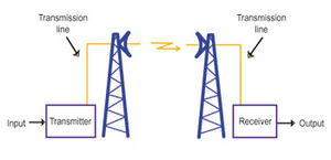
A simple one-way microwave link includes four major elements: a transmitter, a receiver, transmission lines, and antennas. These basic components exist in every radio communications system, including cellular telephones, two-way radios, wireless networks, and commercial broadcasting. But the technology used in microwave links differs markedly from that used at the lower frequencies (longer wavelengths) in the radio spectrum. Techniques and components that work well at low frequencies are not useable at the higher frequencies (shorter wavelengths) used in microwave links. For example, ordinary wires and cables function poorly as conductors of microwave signals. On the other hand, microwave frequencies allow engineers to take advantage of certain principles that are impractical to apply at lower frequencies. One example is the use of a parabolic or “dish” antenna to focus a microwave radio beam. Such antennas can be designed to operate at much lower frequencies, but they would be too large to be economical for most purposes.
In a microwave link the transmitter produces a microwave signal that carries the information to be communicated. That information—the input—can be anything capable of being sent by electronic means, such as a telephone call, television or radio programs, text, moving or still images, web pages, or a combination of those media.
The transmitter has two fundamental jobs: generating microwave energy at the required frequency and power level, and modulating it with the input signal so that it conveys meaningful information. Modulation is accomplished by varying some characteristic of the energy in response to the transmitter’s input. Flashing a light to transmit a message in Morse Code is an example of modulation. The differing lengths of the flashes (the dots and dashes), and the intervals of darkness between them, convey the information—in this case a text message.
The second integral part of a microwave link is a transmission line. This line carries the signal from the transmitter to the antenna and, at the receiving end of the link, from the antenna to the receiver. In electrical engineering, a transmission line is anything that conducts current from one point to another. Lamp cord, power lines, telephone wires and speaker cable are common transmission lines. But at microwave frequencies, those media excessively weaken the signal. In their place, engineers use coaxial cables and, especially, hollow pipes called waveguides.
The third part of the microwave system is the antennas. On the transmitting end, the antenna emits the microwave signal from the transmission line into free space. “Free space” is the electrical engineer’s term for the emptiness or void between the transmitting and receiving antennas. It is not the same thing as “the atmosphere,” because air is not necessary for any type of radio transmission (which is why radio works in the vacuum of outer space). At the receiver site, an antenna pointed toward the transmitting station collects the signal energy and feeds it into the transmission line for processing by the receiver.
Antennas used in microwave links are highly directional, which means they tightly focus the transmitted energy, and receive energy mainly from one specific direction. This contrasts with antennas used in many other communications systems, such as broadcasting. By directing the transmitter’s energy where it's needed—toward the receiver—and by concentrating the received signal, this characteristic of microwave antennas allows communication over long distances using small amounts of power.
Between the link’s antennas lies another vital element of the microwave link—the path taken by the signal through the earth’s atmosphere. A clear path is critical to the microwave link’s success. Since microwaves travel in essentially straight lines, man-made obstacles (including possible future construction) that might block the signal must either be overcome by tall antenna structures or avoided altogether. Natural obstacles also exist. Flat terrain can create undesirable reflections, precipitation can absorb or scatter some of the microwave energy, and the emergence of foliage in the spring can weaken a marginally strong signal, which had been adequate when the trees were bare in the winter. Engineers must take all the existing and potential problems into account when designing a microwave link.
At the end of the link is the final component, the receiver. Here, information from the microwave signal is extracted and made available in its original form. To accomplish this, the receiver must demodulate the signal to separate the information from the microwave energy that carries it. The receiver must be capable of detecting very small amounts of microwave energy, because the signal loses much of its strength on its journey.
This entire process takes place at close to the speed of light, so transmission is virtually instantaneous even across long distances. With all of their advantages, microwave links are certain to be important building blocks of the world’s communications infrastructure for years to come.
Link Block Diagram
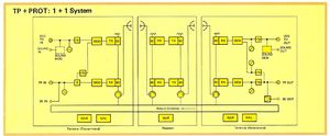
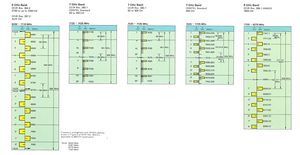
This diagram is from an NEC 500 series microwave link system (circa 1983) and shows one equipment block path. The "return direction" block is the reverse of that detailed in the main diagram.
Regulatory and Licensing
Each country has a varying requirement for the licensing of microwave radio links. In most cases this license only addresses the transmitter, but in the same instance, it offers regulatory protection to any inteference that may affect the microwave receiver.
License costs are usually linked with the size of the spectrum occupied by the transmitter signal - and are often directly influenced by some of the spectrum lease costs realized by the local regulator, eg FCC, ACMA, PTT's etc.
Microwave Radiation Safety
A safety aspect of microwave radio EMR radiation is also defined by standards and guidelines, and often human exposure 'exclusion' zones exist around the front of microwave dish antennas, horns and dielectric antennas. Personnel safety must also be considered around open waveguide ends and waveguide switches with unterminated ports. Refer to other material at the GHN on EMR Safety.
Treating microwave radiation safety in a conservative manner is always prudent, never look down open waveguide, never stand in front of a microwave antenna.
Frequency Planning
In the older Frequency Division Multiplex (FDM) microwave radio link systems, only a single pair of frequencies were allocated to the whole link network, with an alternating polarisation isolation arrangement from more distant stations in the network. This meant that at a single microwave repeater station, the link transmitters operate on the same frequency, but with antennas pointed in different directions, and with opposite antenna polarisation.
The same frequency planning logic still applies to modern digital microwave radio links, with a close eye on the 'emission' bandwidth / designator. Frequency planning may also have restrictions from the Regulator (FCC / ACMA / Ofcom / PTT's), so extensive consultation is required before any commitments can be made.
Microwave Radio Link Planning
The design and construction of a microwave radio link network is based on a number of factors. These include:
- Distance between microwave radio terminals;
- Terrain properties, eg bodies of water, cliffs, forests, snow;
- Frequency of operation, often governed by licensing costs, frequency availability, planned distances and even susceptibility to rain fading;
- Interference management to the microwave link receiver. Generally managed by allocating a clear frequency pair by the Regulator, but for frequency bands 'sold at auction' or with delegation, eg Defence communications and large carriers, this becomes the management responsibility of the band licensee/owner;
- Fading, dispersion and multipath distortion;
- Size of antennas, feedline properties, need for towers and masts, and for high gain antennas - even the stability (both tilt and torsional properties) of the supporting mast must be engineered to avoid the antenna beam being mis-directed due to wind or ice on the structure;
- Management of moisture inside external waveguides;
- Management of equipment, power and security alarms, remote control switching and order wire systems.
- Council, Local Government, FAA, CASA and community development permissions governing visual and controlled airspace intrusions;
- Cost of equipment and cost benefit analysis including equipment maintenance;
- Satellite communication links are also classed as microwave radio links, but given their minimal exposure to atmospheric conditions, these type of microwave links can operate at minimal fade margins, ie having minimal contingency in the level of received signal strengths;
- Availability of equipment, spares, maintenance, test equipment and skilled staff;
- Sun transits for microwave link receivers facing at the eastern or western horizons. The issue here is that the "sun noise" will often overwhelm broadband microwave receivers, generating what is called a 'sun transit outage'. Same deal for satellite communication links as well.
Manufacturers of Microwave Link Equipment
In no specific order, these include:
- - NEC
- - Ericsson
- - Nokia
- - Marelli
- - Marconi
- - GT&E
- - GE
- - Phillips
- - Rohde & Schwartz
- - Kuhne
- - Codan
- - Alcatel
- - Fujitsu
- - Siemens
- - ATI
- - Hughes
Further Reading
NEC 500 Series Microwave System Brochure Dec 1979 (pdf, 1.3Mb)
Microwave Link Planning Program - An 1985 assignment written around a microwave radio link planning piece of software, using GWBasic under DOS 2.2 by David Burger


