Horizontal Drilling
Early steps in steering technology
The original version of this article was created by Francesco Gerali, 2020 Elizabeth & Emerson Pugh Scholar in Residence at the IEEE History Center
It is recommended this article be cited as:
F. Gerali (2020). Horizontal Drilling, Engineering and Technology History Wiki. [Online] Available: https://ethw.org/Horizontal_Drilling
Directional drilling is the practice of boring deviated/slant wells, where the steering angle varies from a 1° to 80° range. Known and used by petroleum engineers since late 19th century, the purpose of this technology was to drill wells at multiple angles to reach petroleum and gas reservoirs in a more precise and profitable manner.
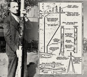
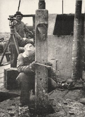
In the early 1900s, the main prerequisite that enabled drilling steering technologies to gain visibility was the need to dig petroleum and water wells not vertical to enhance well production. The early market of deviated/slanted wells was limited and expensive; it did not hit the interest of drillers until the late 1920s. In the 1930s-1940s, only a cadre of crews of drillers in the world had the skills and the knowledge to make a bit rotate a hundred meters underground at the end of a steel drill pipe, slanting its path by means of specifically conceived tools (e.g., whipstocks)[1] to reach reservoirs (FIG.1-2).
Experience gained with rotary drilling in the late 1880s in the United States had established several principles for the configuration of drilling survey equipment to avoid direction discontinuity and the subsequent drilling of crooked holes[2] (FIG.3). The measuring of the inclination of a well, called also “deviation of the vertical”, requires a simple pendulum; on the other hand, the gauging of the magnetic azimuth[3] - the direction with respect to the geographic grid in which the well runs from the vertical, was more difficult. Magnetic fields could be used, but they could be influenced by the metallic tools utilized in drilling equipment. A turning point in deviation detection was the modification of small gyroscopic compasses[4] manufactured by the Sperry Corporation[5] in late 1920s, which was producing similar compasses for aviation.
The progressive cavity pump principle of Moineau
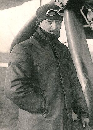
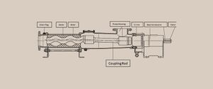
Another major scientific element of innovation matured in Europe in 1930, when the French engineer René Moineau (FIG.4) discovered the principle of the progressive cavity pump, which shortly after led to the development of downhole positive displacement motors. They had a huge potential, and indeed became the most effective deviation tool used in directional drilling. But the industry in the 1930s was not yet ready to adopt such costly, and a still not perfected machine, and the whipstocks remained the primary steering mechanism for directional drilling until mid-1950s. The first modern, reliable and costly effective downhole drilling mud motors was designed and manufactured in 1958 by the Dyna-Drill company. Since then, directional drilling used a deflector joint combined with a downhole steerable mud motor,[6] known also as a Progressive Cavity Positive Displacement pump, PCPD (FIG.5). The first directs the bit in a different direction from the wellbore vertical axis when the drill string is not rotating. Injecting high-pressure fluxes of drilling fluids into the mud motor, which impose the rotative motion to the bit. These allowed the bit to be rotated on the bottom of the hole, while most of the drill pipe was held stationary. A piece of bent pipe named bent sub[7] between the stationary drill pipe and the top of the motor allowed the direction of the wellbore to be changed without needing to pull all the drill pipe out and replace it with further equipment. After the achievement of the right angle is completed, the mud motor is stopped, the drill string is set in motion to continue the drilling though the main drilling motor placed at the base of the derrick.
The need for precision
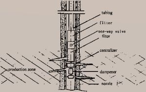
Drilling sensors and positioning technology much helped the efficiency and effectiveness of directional drilling technology. Modern tools used in achieving precision for down hole directional drills include Bottom Hole Assembly[8] (or BHA configurations), three-dimensional measuring devices, mud motors and specialized drill bits (FIG.6). Counter-experience had also given early directional drillers ("DD's") principles of BHA design and drilling practice that would help to correct a crooked hole to be nearer to the initial vertical line. Combined, these survey tools and BHA designs made directional drilling possible, safe, and relatively affordable.
In the 1970s, the design and production of down hole drilling motors found new momentum. Combined with the development of measurement while drilling devices like mud pulse telemetry,[9] networked or wired pipe[10] or electromagnetic telemetry,[11] - which allows tools down hole to send directional data back to the surface without disturbing drilling operations - directional drilling became easier to put into practice. That dramatically improved the trust of investors and the number of drilling crews capable to operate such expensive and delicate toolset.
Drilling directionally with a motor requires occasionally "sliding" the drill pipe, which means stopping the pipe rotation and pushing the pipe in the hole as the motor cuts a curved section of hole in the desired direction. The sliding can be difficult in some formations, and it is almost always slower and therefore more expensive than drilling while rotating. Also, hole cleaning during sliding is less effective. In the light of these odds, the ability to control wellbore direction while rotating is always preferred by well operators.
Several companies have developed tools which allow directional control while rotating. These tools are referred to as Rotary Steerable Systems[12] (RSS), which allowed access to directional control in formations that in the past were classified as inaccessible or uncontrollable.
Horizontal Drilling
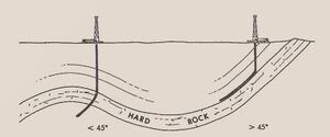
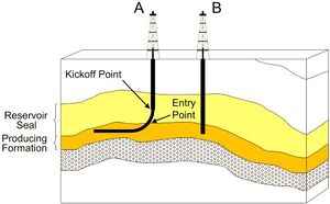
Horizontal drilling is the main subset of directional drilling, and it refers to any wellbore that exceeds 80°, including angles higher than 90°, (drilling upward). Horizontal drilling is the process of drilling a well from the surface to a subsurface location just above the target oil or gas reservoir, called the kickoff point,[13] then deviating the wellbore from the vertical plane around a curve to intersect the reservoir at the entry point with a near‐horizontal inclination and remaining within the reservoir until the desired bottom‐hole location is reached (FIG.7).
In petroleum historiography the earliest evidence of horizontal drilling technology dates back to 8 September 1891 when the Patent Number US459,152A[14] and titled “FLEXIBLE DRIVING SHAFT” (presented in August 1889) for the use of flexible shafts to rotate drilling bits was awarded to John Smalley Campbell in the United States. A flexible shaft was a device for transmitting rotary motion between two objects that are not fixed relative to one another. Typically, such devices consisted of a rotating wire rope or coil that is flexible but has some torsional stiffness, which could have a bending protection covering. The latter did not rotate but helped to transmit considerable motion power also with a low input from the well mouth.
The first horizontal petroleum well was successfully drilled in 1929 in Texon, Texas; in 1944 in the Franklin Heavy Oil Field, Venango County, Pennsylvania was drilled. China also tried horizontal drilling as early as 1957, followed by the Soviet Union. During the 1970s, the term massive frac[15] was coined to describe hydraulic fracturing operations - completed through horizontal drillings - executed into deeper, high temperature formations and utilizing about 3.8 million liters of fluids, more 1361 metric tons of sand, and an heterogeneous mix of additives.
However, it had limited practical application until the early 1980s, with the advent of improved downhole drilling motors and other necessary supporting equipment, materials and technologies. Notably, downhole telemetry equipment brought some applications within the imaginable realm of commercial viability. Tests, which indicated that commercial horizontal drilling success could be achieved in more than isolated instances, were carried out between 1980 and 1983 by the French firm Elf Aquitaine[16] in four horizontal wells drilled in three European fields (FIG.8). British Petroleum[17] would subsequently use horizontal drilling techniques in Alaska’s Prudhoe Bay Oil Field.
The technology acquired a fundamental relevance in the early 1990s when it proved to be instrumental to the establishment of the newly founded unconventional oil and gas business. With the advent of horizontal drilling and well stimulation techniques, among many other important insights and innovations, the exploitation of unconventional resources boomed. Those are characterized as hydrocarbon reservoirs that have low permeability and porosity, rendering production of gas and oil from such reservoirs difficult (tight gas,[18] coal bed methane,[19] methane hydrates,[20] shale gas,[21] shale oil,[22] heavy oil,[23] and tar sands[24]). In this kind of operations, the horizontal wells drastically increased the production (20 times more than that of its vertical counterpart) by drilling across the longitudinal plane of the productive formation. The unconventional sector is considered by some to be the oil and gas drilling technological revolution of the 21st century.
See also
References
Brantly, J E. History of Oil Well Drilling.
Clark, J.B. 1949. “A Hydraulic Process for Increasing the Productivity of Wells”. Journal of Petroleum 1 (1): 1–8.
Gallegos, T.J. and Varela, B.A. 2015. Trends in Hydraulic Fracturing Distributions and Treatment Fluids, Additives, Proppants, and Water Volumes Applied to Wells Drilled in the United States from 1947 Through 2010: Data Analysis and Comparison to the Literature. United States Geological Survey Scientific Investigations Report 2014–5131. Reston, VA: U.S. Geological Survey, 15 p. doi:https://doi.org/10.3133/sir20145131.
Gensheng, Li, Huang, Zhongwei, Debin, Zhang, Jilei, Niu. 2006. Combined High Pressure Water Jetting and Acidizing Method for Perforation Cleaning and Formation Treatment: Mechanisms and Applications. Petroleum Science and Technology 24(5):459-468.
Helms, Lynn. 2008. “Horizontal Drilling”. DMR Newsletter 35, no. 1
Hubbert, M.K. and Willis, S.G. 1957. “Mechanics of hydraulic fracturing”. Transactions of Society of Petroleum Engineers of AIME 210: 239–257.
Journal of Petroleum Technology. 1990. “Horizontal drilling contributes to North Sea development strategies”. Journal of Petroleum Technology 32: 1154.
Naughton, Honora Mary. 1999. The Ambiguous Partnership: Elf Aquitaine and the French Government 1976-1986. The London School of Economics and Political Science, University of London. PhD. Thesis.
Testa, S.M. 2015. “Historic Development of Fracturing and Hydraulic Fracturing, Part II: The Birth of the Petroleum Engineer (1930s–1950s)”. Pacific Section American Association of Petroleum Geologists Newsletter, March–April 2015, pp. 12–15.
Testa, S.M. 2015. “Historic Development of Fracturing and Hydraulic Fracturing, Part IV: The Rise of the Unconventionals (1990s‐Present)”. Pacific Section American Association of Petroleum Geologists Newsletter, September–October, 2015.
Further Reading
- ↑ https://www.slb.com/-/media/files/oilfield-review/2-whipstock-2-english
- ↑ https://www.drillingmatters.org/glossary/crooked-hole/
- ↑ https://www.mindat.org/glossary/magnetic_azimuth
- ↑ https://www.uh.edu/engines/epi3227.htm
- ↑ https://invention.si.edu/sperry-gyroscope-company-division-records-1910-1970
- ↑ https://www.petropedia.com/definition/5706/downhole-motor
- ↑ https://onepetro.org/DC/article-abstract/1/05/390/74430/The-Remote-Controlled-Multiangle-Bent-Sub-for?redirectedFrom=fulltext
- ↑ https://www.drillingmanual.com/2017/11/bottom-hole-assembly-bha-components.html
- ↑ https://www.researchgate.net/publication/325532912_A_review_of_mud_pulse_telemetry_signal_impairments_modeling_and_suppression_methods
- ↑ https://core.ac.uk/download/pdf/270309777.pdf
- ↑ https://www.springer.com/gp/book/9783030215361
- ↑ https://www.drillingmanual.com/2017/11/rss-rotary-steerable-system-autotrak-baker-hughes.html
- ↑ https://glossary.oilfield.slb.com/en/terms/k/kick-off.aspx
- ↑ https://patents.google.com/patent/US459152A/en
- ↑ https://www.sciencedirect.com/topics/engineering/massive-hydraulic-fracturing
- ↑ https://www.musee-pompe.fr/enseignes-a-travers-monde/groupe-total/elf-aquitaine-espoirs-de-france/
- ↑ https://books.google.it/books/about/The_History_of_the_British_Petroleum_Com.html?id=PduotC73nh0C&redir_esc=y
- ↑ https://www.sciencedirect.com/topics/earth-and-planetary-sciences/tight-gas
- ↑ https://serc.carleton.edu/research_education/cretaceous/coalbed.html
- ↑ https://www.energy.gov/fe/science-innovation/oil-gas-research/methane-hydrate
- ↑ https://www.sciencedirect.com/topics/engineering/shale-gas
- ↑ https://www.sciencedirect.com/topics/engineering/shale-gas
- ↑ https://pubs.usgs.gov/fs/fs070-03/fs070-03.html
- ↑ https://www.americangeosciences.org/critical-issues/faq/what-are-tar-sands
