First-Hand:A Brief Description of the Early Implementation of Ethernet Networking at CBS Television
Submitted by Mark Carey
I retired in December of 2021 after a 56-year broadcast engineering career. I started at a small market radio station when I was twelve thanks to some generous mentors who let a kid in to learn and help. While there I was both an engineer and an announcer. I attended Eastern Illinois University and then transferred to the University of Illinois where I graduated with a BS in Electrical Engineering. While at the U of I, I taught audio production in the College of Communication for three years. I also designed and built two audio studios used for the students enrolled in the class. Following graduation, I worked at CBS Television Engineering in New York City for nearly 20 years. I designed audio and video systems for broadcasting for the CBS Television Network and other CBS facilities around the country. Following CBS, I designed systems for Spacecom Systems and Dish Network Satellite Uplink facilities in the southern suburbs of Chicago. Later, I worked as a consultant for two federal agencies and a major bank and then designed new high-definition systems for a Chicago television station. I finally retired from a large global consulting company where I designed systems for a huge professional SDI and IP broadcast facility for company broadcasts.
This is a brief description of the early implementation in 1988 of Ethernet networking in broadcast systems at CBS Television in New York, New York. It is written from my personal experience as I remember 33 years later. This was one key part of a major new facility that was my favorite and most rewarding project of my career. It was also the largest and the most challenging project. A bonus was it was fun.
The CBS Broadcast Origination Center (BOC), a part of the CBS broadcast distribution system, was a facility in New York City that provided multiple television programs continuously 24 hours a day, seven-days-a-week. It also integrated commercials into live or recorded programs. Programs included those of the CBS Television Network, the CBS Television Pacific Network (PACNET), the CBS-owned station in New York City (WCBS-TV), and several contract syndicators. BOC went online July 22, 1991, at an initial cost of over $25 million. It was replaced in December 2012.
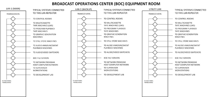
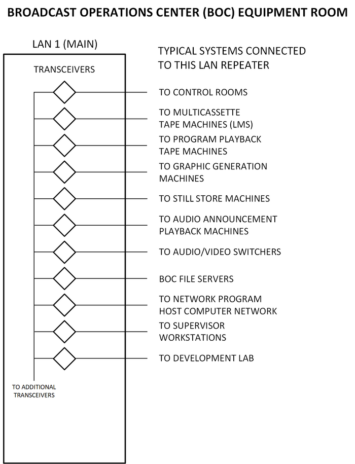
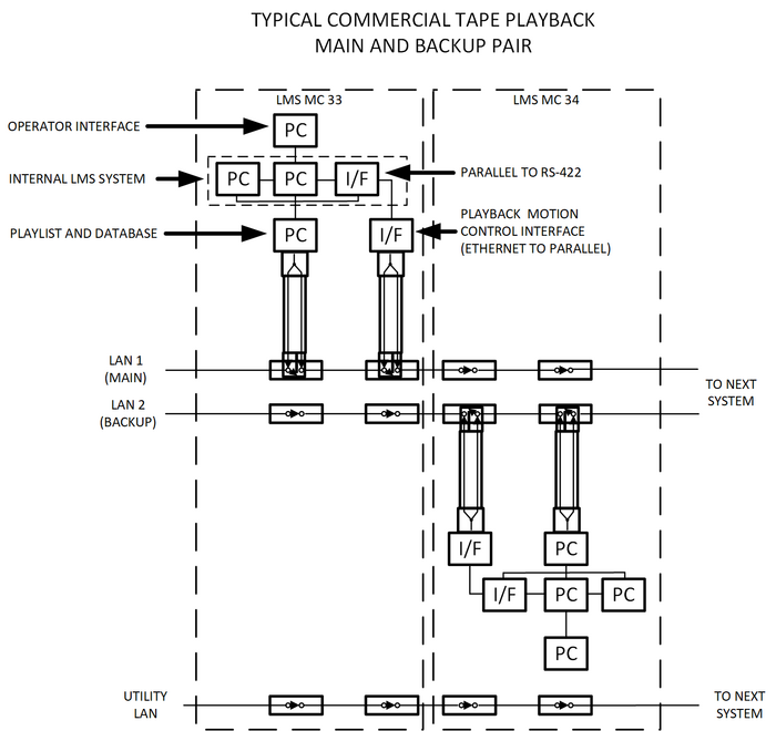
I became involved with BOC as an "in-house" broadcast automation consultant in 1987. I had two previous smaller broadcast automation projects. I joined the project full time in 1988. I designed or contributed to the design of the control rooms, switching systems, automation system, commercial playback systems (Sony Library Management Systems or LMS) and support systems. Each of these systems had multiple interfaces with microprocessors and PCs plus there were gateways to minicomputers that produced the broadcast schedule. They all connected via multiple segments of three Ethernet local area networks. I did the original concept development and design for the BOC local area network (LAN). Prior to this I had only used one small network with about six devices. I had a very steep learning curve for the BOC networks. The network was divided into three LANs named LAN 1, LAN 2, and Utility. The main systems were assigned to LAN 1 and the backup systems were assigned to LAN 2. The utility LAN was for testing or to replace a LAN during repairs. New software and hardware were tested and qualified for use by placing a switcher (or switchers), LMS machines, file servers, and other systems on the utility network. A system of centrally located LAN repeaters for LAN 1, LAN 2, and Utility were used to isolate the three LANs into multiple segments of each to avoid having a fault on one LAN disrupt the complete LAN or other LANs.
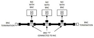
Back in the “dark ages” of computer networks (the BOC network design started in 1988), Ethernet local area networks were limited to two options Thin Ethernet and Thick Ethernet. Cat5 and Cat6 networks were a few years in the future and later replaced the networks described here. Thin Ethernet or Thinnet (also called ThinNet) was officially called 10 Base-2. It used an RG 8A/U (0.4-inch diameter) coaxial cable. The cable ends were terminated with BNC connectors. Each device on the network was connected to the network through a BNC "T" and each end of the network had a 50 Ohm terminator attached. Each node on the network had to be a minimum of 0.5 meters (1.5 feet) apart, and the overall length of the network segment must be less than 185 meters (606 feet).
Thinnet was a more flexible (pun intended) and less expensive alternative to Thick Ethernet or Thicknet, officially called 10 Base-5. It used a 0.5-inch diameter cable coaxial cable, but with extra braided shielding. It was very stiff and connecting to it was expensive and time consuming.
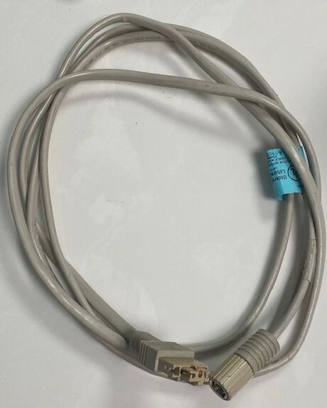
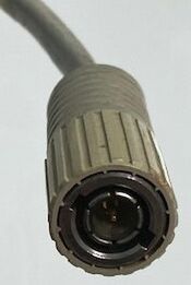
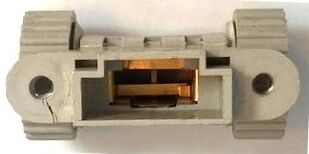
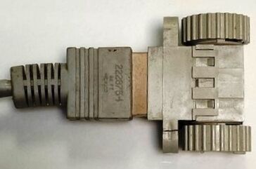
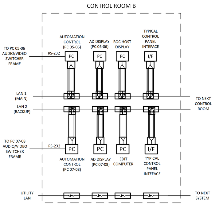
The network required the “T” node to be connected directly at the device. Connecting the device to the “T” via a cable would disrupt the network due to signal reflection in the cable to the “T”. One other problem for many facilities, especially CBS, was the need to be able to disconnect a system or device from the network for replacement or maintenance without disrupting the LAN segment. We also wanted to be able to quickly reconfigure the LAN to work around cable, connector, or other problems. The “T” was often in a hard-to-reach location. It was important to avoid disruptions while disconnecting and reconfiguring the LANs. I found a special Thinnet Ethernet patch cable and receptacle that made it possible to patch devices from one LAN to the other without taking either the LAN or devices off-line. A receptacle for each LAN was mounted on a panel behind or near each device for easy access.
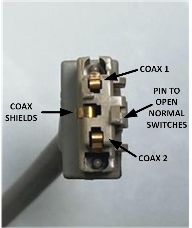
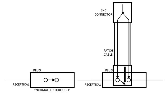
The system consisted of a specialized tap assembly or receptacle which connected to the coaxial backbone cable. Inside the tap was a "self-normalling” switch. If the patch cable was not plugged in the switch was closed or “normalled through” so the signal passed along the coaxial cable. There were two coaxial cables inside the patch cable forming the equivalent of a BNC "T" adapter with both coax cables tied as a single node at the BNC end. When a patch cable was plugged into a tap it opened the switch. Each side of the tap was then electrically connected to each coaxial cable in the patch cable, which connected the signal to the node and then back to the other side of the tap. This resulted in a continuous network and the node still connected at the device. Each broadcast device on the BOC LAN as well as the segment repeaters had a patch panel with a plug for the device and a receptacle for each of the LANs. BOC was the first time CBS used a large shared data network for controlling broadcast equipment. In the past, RS-232, RS-422, and parallel port control lines were used. The three LANs and the special Ethernet connectors were two key selling points for using Ethernet in BOC.
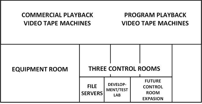
The following are drawings for the BOC local area network. These depict some of what I have described. These are based on what I recall about three decades later.
As I wrote before, this new facility that was my favorite and the most rewarding project of my career. It was also the largest and most challenging project. Not only was it fun I got paid to have fun.
