The Beginnings of Naval Fighter Direction - Chapter 5 of Radar and the Fighter Directors
By David L. Boslaugh, Capt USN, Retired
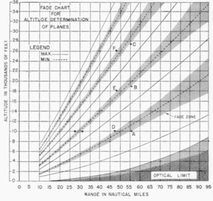
In the Royal Air Force the facilities and procedures for fighter direction were methodically worked out under the direction of Air Chief Marshal Dowding. However, fighter direction in the Royal Navy seems to have grown from the bottom up. The first use of naval radio location “in anger” was at the Royal Navy’s Scapa Flow base in the Orkney Islands north of Scotland, but it would be for gunnery direction rather than fighter direction. In this instance, in late March 1940, the anti-aircraft cruiser HMS Curlew, newly fitted with her Type 79Z RDF set, was moored at the flagship’s buoy when her RDF officer Lieutenant John R. Hodge detected an unidentified flight 50 miles to the south. He was able to judge their approximate height from their fade ranges, and he could tell from the blip pattern that they were “many.” Curlew hoisted flags warning the anchored fleet of their approach. With a few marks on a plotting board, Hodge was able to estimate the attacker’s speed and estimated time of arrival. Then Curlew hoisted a yellow flag, meaning air attack was expected in five minutes. Approximately nine twin-engine bombers soon appeared and were visually confirmed as German, upon which the assembled ships threw up a wall of bursting AA projectiles in front of the formation. The attackers turned back and dropped their bombs in the sea. Radio location was wrapped in layers of secrecy, and Curlew soon got the reputation that she could forecast air attacks. LT Hodge would later write, “In Scapa we soon devised a special plotting board to enable us to plot both at sea and in Harbor. It was from this board that we worked out the speed of approaching planes.” [29, pp.50-51]
On 9 April 1940 Germany invaded Norway and Denmark, and all eight of the RN ships fitted with the Type 79 RDF took part in the relief campaign. These were the battleships HMS Rodney and HMS Valiant, the heavy cruiser HMS Suffolk, the light cruiser HMS Sheffield, and the AA cruisers HMS Carlisle, HMS Coventry, HMS Curacoa, and HMS Curlew. The aircraft carrier HMS Ark Royal was also in the Norwegian campaign, and even though she was not equipped with RDF, her Air Signals Officer Lieutenant Commander Charles Coke is generally credited with originating naval fighter direction. The cruisers Sheffield or Curlew usually accompanied Ark Royal and sent their RDF detection and tracking reports to the carrier via wireless telegraph Morse code. Coke had no fighter direction facilities other than a corner of the carrier’s Bridge Wireless Office, a telegraphist who wrote down the RDF reports from the cruisers, and a “Bigsworth Board.” The Bigsworth Board was a plotting device used by aircraft navigators. It was about two feet across and had an attached parallel pantograph arm. Coke used the board to plot the track of the incoming raider, to compute its speed, and later, to compute the heading and speed required of a fighter to intercept the raider. Ark Royal carried a complement of Blackburn Skuas that were used both as fighters and dive bombers. They were crewed by a pilot and a rear-seat gunner/radio operator, who used Morse code rather than voice radio. [29, p.52, p.56] [62, pp.1- 2]
Coke was also adept at Morse code and sent his information to Ark Royal’s fighters by wireless telegraph. In the beginning, he sent only the raider’s location, course, and speed to the fighters, and left it up to the aircrew to determine a heading and speed for intercept. Coke called this the “informative method” of interception. As he gained more experience he found he could maintain a fairly accurate track of the friendly fighter by a combination of dead reckoning and periodically requesting the cruiser to get an RDF measurement on the fighter. He was then able to tell the fighter what heading and speed, and some times altitude, he should fly for intercept. Coke called this the “directive method.” The whole process, from RDF detection to receipt of order in the fighter took about four minutes, which called for Coke to anticipate attacker and fighter locations by four minutes. The top speed of the Blackburn Skua was around 225 mph, whereas the opposing German Junkers, Ju 88, and Heinkel He 111 bombers could exceed 270 mph. This added another dimension of difficulty to Coke’s fighter direction. The fighter had only one chance, and could not pursue. The goal was to vector the fighter to a position ahead and above the bomber, and up-sun if possible. In May and June 1940, at the latitude of the Norwegian Campaign, daylight lasted for almost all of the 24-hour day, giving the Germans daylong opportunity for attacks on the British fleet. It is said that Coke rarely left his post in the Ark Royal bridge during those two months. In the meantime, the newly built carrier HMS Illustrious was commissioned on 25 May 1940, and would be the first RN carrier fitted with the Type 79Z radio location set. She went to a work-up location near Bermuda to exercise her air squadrons, and in the process tried out the informative method of fighter direction. [29, pp.56-57, p.63] [62, pp.2-3]
By 11 June 1940, the AA cruiser Carlisle had transited the Mediterranean and was in the Red Sea off Aden. Nearby ashore, was a squadron of RAF Gloster Gladiator biplane fighters that did not have the benefit of radio location equipment. Arrangements were made that Carlisle, with her RDF equipment, would provide fighter direction support to the squadron, and early that morning the perfect opportunity arose. Carlisle’s radar operator detected a flight of twelve Italian Savoia-Marchetti SM.79 bombers at about forty-five miles range flying at 5,000 to 6,000 feet. Her gunnery officer, Lieutenant F. C. Morgan, vectored the Gladiators out to meet the oncoming raid. Between ship and shore based guns and the Gladiators, nine of the bombers were destroyed in the air and the three remaining were forced down in the desert where their crews surrendered. [29, pp. 62-63]
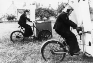
LCDR Coke completed his tour in Ark Royal in early 1941 and visited the Naval Air Division in the Admiralty in May to arrange for his next duty. During the discussions he outlined his fighter direction experiences and put in a strong plea for formal training of future naval fighter directors. There may be truth in the old adage, “be careful what you ask for, you may get it.” He was later called in and told that his next tour would be to establish a fighter direction school. For school facilities he was given space in the control tower at RN Air Station Yeovilton, some 12 miles south of ancient Glastonbury Abbey. Coke’s first action was to “borrow” a ground control intercept RDF set from the Royal Air Force and have it installed at Yeovilton. He set up a three-week course, of which half would be lectures and half practical exercises in fighter direction. For the latter, Coke, by then a Commander, had hoped to get sufficient aircraft services that students could get the experience of using the RDF in live intercepts, however, not enough aircraft services were available. He had to find a way to simulate both attackers and defending fighters, and his solution was ice cream vendor’s tricycles. He equipped the trikes with a compass, a radio and a metronome to allow the bomber and fighter trike “pilots” to precisely control their pedaling speeds in accordance with orders from a student fighter direction officer. The “fighter” tricycles also had slotted front shields to restrict their pilots’ visibility to a few yards so that they could not see their target until they were within simulated visual range of their quarry.
A polar grid system was laid out on the ground so that an observer stationed above the grid could act as an RDF operator by phoning in ranges and bearings of bomber and fighter trikes. These were plotted, and students computed the speed and heading vectors to bring the fighter trikes into attack positions on the bomber trikes. The students would learn the RAF fighter direction lexicon to coach the fighters into position. Coke held his first class with eight students in July 1941, and would later report that at first this simulation was an object of ridicule, and that many student FDOs were not happy pedaling trikes on a hot summer day. That is, unless one of their two female Women’s Royal Naval Service (WRNS) was “flying” an attacking bomber trike, then the student would usually pedal faster than ordered by the student FDO. In the long run the system was very effective in turning out future FDOs, and at practically no cost. [62, pp.3-4] [42, p.96]
The Tizard Mission
In his role as head of the Committee for the Scientific Survey of Air Defense (the Tizard Committee), Professor Henry Tizard was privy to most of the British scientific and engineering breakthroughs that had potential value for national defense. He was also aware that it was going to be a long war, and that Great Britain was probably going to be highly dependent on American manufacturing capacity to keep the British supplied with war material. He felt it could be advantageous to Great Britain to share their secret scientific and engineering breakthroughs with the Americans to enhance U.S. manufacturing capability. Conversely, the Americans might have technical secrets that could be of value to the U.K. In early May 1940 Tizard made a “sharing” proposal to the members of the Tizard Committee, who generally agreed, and recommended the idea be forwarded to the Prime Minister. Churchill agreed, and on 8 July 1940 Lord Lothian, the Ambassador to the United States, and President Roosevelt signed a joint memorandum setting up a technical exchange to be called the British Technical and Scientific Mission. Tizard would be the leader and he would be accompanied by Professor John Cokcroft of Army Research; Mr. A. E. Woodward-Nutt as recording secretary; Dr. E. G. Bowen, developer of the airborne intercept sets; and three senior military officers, each representing a service branch. They would carry a black metal deed box that included secret documentation on Chain Home, naval radio location, airborne radio location, the Whittle jet engine, gyroscopic gun sights, aircraft engine superchargers, a radio based projectile fuse, plastic explosives, the twelfth cavity magnetron off the production line, and other breakthroughs. On 5 August the U.S. Navy’s Chief of Naval Operations issued instructions on how the participating naval activities were to work with the visiting British delegation. In general, they were not to hold back. Matters concerning U.S. naval aviation and radio location were to be discussed freely. [9, pp.159-160] (20, p.102]
Tizard went by air to the U.S. in late August to make advance arrangements, and the rest of the group traveled by ship, arriving in Washington, D.C. on 8 September 1940. On 12 September they had their first meeting with their American counterparts in the Army and Navy Building on the Washington Mall. There were some mutual surprises that day, for both found the other had operational radio location sets ashore and afloat. Security on both sides about radio location had been good. The British, who had been using separate antennas for transmitting and receiving, were very pleased to see Robert Page’s duplexer switch that allowed receiver and transmitter to share one antenna. The Americans were astounded by the cavity magnetron. A few days later the British delegation visited the Naval Research Laboratory (NRL), and Page was disappointed to learn that they already had a plan position indicator (PPI) display in production. Warrant Radio Electrician Irvin L. McNally, who was studying radio location at the Lab’s Warrant Officer’s Engineering School, had been invited to sit in on the meeting, and that night one of Page’s engineers showed McNally the experimental PPI they were testing. The British had beat them to the punch on that one. There would be further fallout from the Tizard Mission. Now that both sides knew that the other was operationally using radio location, the British invited U.S. services to send observers to learn how radio location was used in fighter direction. This resulted in a number of U.S. naval aviators being temporarily assigned to RAF and RN squadrons, and usually two would attend each three-week fighter direction course at the Yeovilton Fighter Direction School. By August 1941 the Royal Canadian Air Force had established a five-week radio location course at their radio school in Ontario, and U.S. naval personnel were also being sent to that course. [9, pp.160-161] [6, p.23-24] [62, p.4] [13, p.42]
Finally A Name
The British called their secret radio location sets RDF meaning “radio direction finding,” which was an unclassified term because virtually all nations used radio direction finding equipment. To U.K. radio location insiders, RDF really meant “range and direction finding.” The Americans used a number of phrases to identify their radio location projects such as radio location, radio detection, radio direction finding, radio echo, and radio ranging. Most of these designations, however, implied the purpose of the equipment, and when used in correspondence caused the correspondence to be classified secret, causing much special handling, storage, and extra work. In the Office of the Chief of Naval Operations (OPNAV), two Lieutenant Commanders, F. R. Furth and S. M. Tucker, who were in charge of sponsoring and funding the radio location developments were being slowed down by the need to classify a lot of otherwise routine correspondence because some short phrase alluded to the ability to locate things by radio waves. Furthermore, the numerous phrases used to name radio location equipment were causing confusion. What they wanted was a short unclassified acronym to keep as much as possible of their, and other’s, correspondence unclassified. First, they would come up with one official name for the various equipment and projects, and then they would devise an unclassified acronym from that phrase. They decided on “Radio Detection and Ranging” which yielded the acronym “RADAR.” To announce the new acronym, they drafted a letter that the Chief of Naval Operations, Admiral H. R. Stark, signed out on 18 November 1940 to the material bureaus, the Director of the Naval Research Laboratory, and the Chairman of the General Board. Henceforth, the acronym RADAR could be used in unclassified correspondence, dispatches, and conversations. The British would continue to use the acronym ‘RDF’ until 1943, when all the Allies agreed to “RADAR”. [23, p.170]
A RADAR for Smaller Ships
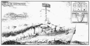
The CXAM Radar Antenna was too large for any ships but aircraft carriers, battleships and cruisers, but OPNAV wanted radars that could be installed in destroyers and smaller ships as soon as possible. In late 1940 the Naval Research Laboratory was tasked to design a version of the CXAM with a smaller antenna and more power output, the prototype of which would be designated XAR. The resulting radar achieved a twenty-times increase in power over the CXAM by use of a new transmitter tube designed expressly for NRL by Eitel-McCullough Co. The receiver was made much more sensitive by use of a General Electric “lighthouse” tube. This allowed the antenna to be reduced from the CXAM’s seventeen-foot square size to a fifteen by four-foot planar array. The set could detect medium sized targets out to sixty miles. Following successful testing on the destroyer Semmes in July 1941, the Bureau of Ships (BUSHIPS) awarded contracts to RCA and General Electric Co. to produce 400 XAR copies. Those made by RCA were designated ‘SA’ and those by GE designated ‘SC-1.’ A BUSHIPS report records that as of 18 December 1941, forty-eight SA/SC-1 radars had been delivered to shipyards, and twenty-seven had been installed. [23, p.183] [1, p.181]
Early Experience With The CXAM
By March 1941 some of the heavy combatants that had been equipped with the CXAM radar were gaining experience in its use. In that month the CO of the carrier Yorktown reported that with the CXAM used in practice exercises, combat air patrols “have been quickly and reliably directed to intercept.” The report also noted that the Fighter Director Officer (FDO) had hardly any room to work, that he needed a trained team of supporting plotters, and he needed a central radar plotting room where he could develop a complete tactical picture. The report continued to say that the chief petty officer radar operators provided their “unrelated and heterogeneous ranges and bearings” by sound powered phone to the bridge, Flag Plot, Air Plot, and Sky Control with no correlation among the various reports. It concluded, “Consequently there must be provided a RADAR plotting team with adequate facilities for assimilating and segregating vital information.”
The Bureau of Aeronautics, the Bureau of Ships, and the Chief of Naval Operations took the report seriously and recommended to the Secretary of the Navy that radar equipped ships be equipped with a radar plotting room that would “be the brain of the organization which protects the fleet or ships from air attack.” The Secretary of the Navy (SECNAV) approved the recommendation in July 1941, and the first “Radar plot” was planned for the island structure of the new-construction carrier Hornet which was scheduled for commissioning in October. Radar Plot was to be accessible to Flag Plot, the Chart House, Air Plot and the room where the radar set was located. It was to be lit in semi-darkness, and it was to be equipped with intra-ship phones, remote radio outlets and/or receivers, a status board for showing information on fighter patrols, bearing indicators, and a “plotting board of generous size and adapted to a clear representation of the movements of several groups of aircraft.” Radar Plot would be manned by a Plotting Officer, two radio men to act as talkers and recorders, and a Fighter Director Officer. Identification friend or foe (IFF) sets were not yet available for USN ships, but it was reported that USS Yorktown was experimenting with a self-developed IFF set. It had also been found that the elevation tilting capability of the CXAM antenna was not very useful in determining target height [11, p.14]
Wildcats and the Thatch Weave
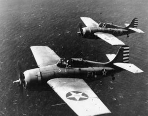
In the spring of 1941 Lieutenant Commander John S. Thatch, skipper of Fighting Squadron 3, based at Naval Air Station (NAS) North Island, San Diego, read a disturbing intelligence report that had come out of the conflict between the Chinese and Japanese. It described a new Japanese fighter, the Mitsubishi “Zero” that could climb at more than 5,000 feet-per-minute and had a top speed of 332 mph. Corresponding figures for the squadron’s Grumman F4F ‘Wildcats were 2,300 fpm and 330 mph. Further, thanks to its very light weight, the Zero could make a much tighter turn than the Wildcat. Thatch realized that if they ever met the Zero in combat they would have to make up the performance difference with superior tactics. He spent many nights using matchsticks on his dining room table to represent airplanes, and after much experimentation he realized two things. First, the present navy practice of using three-plane sections hampered section maneuverability because in tight maneuvers the pilots had to concentrate more on avoiding each other than on keeping track of the enemy. Second, in a two-plane section, the aircraft should be at a much greater separation; a distance equal to the diameter of the tightest turn the airplane could make, called the tactical diameter. That way, if one of the planes was attacked from any direction, the two planes could turn toward each other, and the guns of the wingman would be pointed at the attacker.
Thatch decided to have his squadron try his theory out, using one section to simulate attacking Zero’s. To simulate the Zero’s performance advantage, the attackers would fly at full throttle, whereas the defenders would fly at a little more than half throttle. He had one of his most skillful pilots, Lieutenant Butch O’Hare, simulate the attacking Zero. Many attacks were made, and O’Hare reported that his section was frustrated every time because one of the defending airplanes was always pointed at him in firing position. Another advantage was that no radio coordination was required because the pilot under attack would see his wingman turn toward him, signaling he was under attack and he should turn toward his wingman. The new tactic, combined with the Wildcat’s robust construction, self sealing fuel tanks, and pilot armor, worked. The wartime average kill ratio of Wildcat over Zero would end up as being more than six-to-one. [44, pp.50-51] [3, p.308, p.321][57]
A Tentative Doctrine for Fighter Direction from Aircraft Carriers
The CNO in August 1941, released to the fleets a Tentative Doctrine for Fighter Direction from Aircraft Carriers, which was then embodied in various Commander in Chief, Pacific (CINCPAC) operations orders. The doctrine stated that, in a carrier task force or task group, fighter direction would be under the control of Commander, Air, and this would be a new position reporting directly to the Officer in Tactical Command (OTC). Commander, Air would be in charge of the radar operation of the force and would assign a number to each enemy raid. In the force, ships with radar would have two types of radar tasks. Some would search an assigned sector to detect new targets, and would then pass the location of new targets to other ships that would maintain continuous tracks on assigned targets. Commander, Air was also responsible for:
- Combining own radar information with that from radar guard ships.
- Maintaining a continuous plot of all radar information.
- Evaluating plots and sending alerts of possible air attacks.
- Launching Combat Air Patrol (CAP).
- Assigning CAP to specific locations.
- Directing interception of enemy aircraft.
- Transmitting reports of completed interceptions.
The new doctrine also stated that if an aircraft carrier were present, it should always be designated as the fighter direction ship because carriers have the best facilities and the most skilled fighter direction teams. Voice radio was to be the primary means of communicating fighter direction information, and wireless telegraphy secondary. The locations of all friendly aircraft were to be communicated to all ships in the formation so there could be no confusion with enemy aircraft. CAPT Nicholas J. Hammond, an experienced World War II FDO, noted, “This seems to be so easy, but when an actual battle is in progress, knowing where all the friendlies are is a most difficult task. Obviously, if you know where all the friendlies are, a new ‘bogie’ can only be an enemy.” In December 1941, the CNO issued an updated fighter direction doctrine. There was only one notable change in the new doctrine. British air defense practice called for cessation of shipboard anti-aircraft fire if the CAP could prosecute a successful interception directly overhead, however, the new USN doctrine called for the FDO to instead warn the CAP of AA fire. If the CAP continued on into the firing zone, they did so at their own peril. The CNO stated, “A high volume of well directed anti-aircraft fire is the best defense against enemy aircraft within range.” [12, pp.14-17] [25, pp16-17]
Getting the School Ready
It was 12 September 1941 and a group of twenty-five newly minted ensigns had just graduated from the U.S. Naval Reserve Midshipman’s School at Northwestern University, Chicago, IL. They were comparing the orders they had just received and, strangely, all the orders were identical. They read in part, as follows: “....you will proceed and report for active duty to San Diego, California, and on 1 October 1941 to the Commanding Officer, Naval Air Station, for active duty under instruction in Fighter Director Control, reporting by letter to the Commandant, Eleventh Naval District. The delay in reporting in obedience to these orders will count as leave. Signed/ C. W. Nimitz - The Chief of the Bureau of Navigation”
Their many queries to the Midshipman’s School staff brought no useful explanation as to just what was Fighter Director Control; and to what kind of sea duty would it lead? As ordered, the twenty-five ensigns convened on 1 October in the cavernous space of an empty hanger on North Island Naval Air Station, San Diego. A similar group of ensigns has already gathered on 22 September at Naval Air Station, Norfolk, VA, to receive Atlantic Fleet Fighter Direction Control training.
Lieutenant Commander John H. “Jack” Griffin, welcomed his new charges to the Pacific Fleet Fighter Direction School and introduced himself as their commanding officer. Their executive officer would be Lieutenant (Junior Grade) Henry A. Rowe. Both officers were naval aviators and had made tours in England as observers in RAF and RN squadrons. Both had attended the Yeovilton Fighter Direction School. Rowe had also graduated from the RAF fighter direction school, and had flown from British Carriers. Griffin explained that they were going to learn how to control fighter aircraft in defense of carrier task forces and task groups, and he also let them know that the empty hangar they were standing in was, at the moment, the school’s only asset. Their first job was going to be building and equipping the school’s facilities by begging, borrowing and stealing from his numerous friends and classmates in the San Diego area. Griffin led by example, and he soon had a dedicated group of volunteers helping to equip the classrooms and hangar space. [25, pp.1-2] [34, p.25, p.285]
They needed to obtain and learn a number of Fleet Publications by heart including: U.S. Fleet (USF) 10A: Current Tactical Orders and Doctrine U.S. Fleet; USF 74: Current Tactical Orders and Doctrine U.S. Fleet, Aircraft -Volume One-Carrier Aircraft; and a number of Pacific Fleet Tactical Bulletins. Other written material included aircraft recognition charts and flash cards; the British fighter direction Radio/Telephone vocabulary; British and USN fighter tactics; and performance characteristics of the carrier fighters they would be controlling. In addition to the relatively new Grumman F4F Wildcats, Navy fighter inventory still included the Brewster F2A “Buffalo,” that was being replaced as fast as possible by Wildcats due to the Buffalo’s marginal performance. There were even still a few Grumman F3F biplane fighters on squadron duty. For these aircraft the FDO would need to memorize maximum and cruising speeds, endurance versus speed, rate of climb, armament, and other characteristics. Radar sets were too scarce and valuable to get one for the school, but Griffin did manage to get a CXAM manual from a friend on a ship headed for Pearl Harbor. [25, p.7]
While Griffin and half the students scoured local Navy establishments to “borrow” copies of the needed publications and equipment, other students prepared the hangar area. They painted a series of concentric circles, looking like a target, on the hangar deck. The bull’s eye would represent the center of a task force, a task group, or an aircraft carrier, and the distance between rings would represent a given number of miles depending on the assigned problem. There were ten circles, and for most problems the distance between circles was ten miles. The Yeovilton School had used ice cream vendor’s tricycles to simulate aircraft, but there were no tricycle-borne ice cream vendors in San Diego, and no other supply of trikes large enough to accommodate an adult. Griffin solved the problem by having the supply officer order twelve of the largest children’s tricycles he could find. Then extenders were made to raise seats and handlebars to make the machines fairly comfortable for a grown man. The trikes were equipped with a magnetic compass, a clock, and a table showing how many pedal turns per minute were needed to simulate a speed ordered by a student FDO. The trike “pilot” wore a hood that limited his vision to the visual range a pilot would have in the air; about five miles. [25, p.6]
An overhead catwalk ran across the center of the hangar, and provided a convenient place to set up an azimuth circle and pelorus to allow a student to measure simulated radar bearings of the attacking and defending trikes. Ranges could be measured by range numbers painted on the circles. The student “radar operator” would phone ranges and bearings to a simulated radar plotting room set up in one of the hangar offices. For ship/air communications each “pilot” wore a sound powered telephone headset, and ten phone lines were strung from the radar plotting room to the catwalk and down to the trikes. The phone lines were subject to tangling and were eventually replaced by walkie talkie radios. In the fleet, the future FDOs would be using CXAM, SC-1 and SA radars, so fade zone charts were made up for each radar type showing signal strength as a function of range and altitude. Using a fade zone chart, the “radar operator” on the catwalk would “lose” the attacking target at certain ranges and altitudes, allowing the student FDO to estimate attacker altitude. [25, p.6]
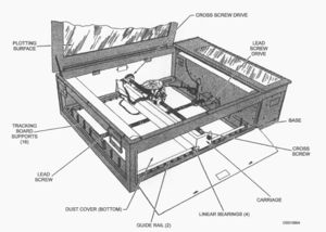
The dead reckoning tracer (DRT) would become one of the FDOs primary tools aboard ship, and Griffin managed to get one for the radar plotting room. Students took over installing the DRT and devising electrical inputs to simulate the heading signal from a ship’s gyrocompass and the speed signal from a ship’s underwater log. The DRT was a desk-sized instrument with a glass top used as a plotting surface. The heading and speed inputs caused a carriage under the glass top to move so that it replicated the ship’s track through the water. A device, universally called the “bug,” was mounted on the carriage, and a light in the bug projected a polar coordinate grid up onto the plotting surface. A large sheet of paper was laid on the glass so that plotters could mark the progression of the ship’s track at periodic intervals. Plotters could also mark the ranges and bearings of targets, as measured by radar or sonar, so that their tracks were also recorded. The DRT had variable range scales that could be set by the operators. If set at a minimum scale of a few thousand yards, the device was very useful in anti-submarine warfare to keep track of submarines, and if set at maximum scale of ten or twenty miles it was similarly useful to support surface gunnery plotting. For the FDOs, the DRT was a most useful fighter direction tool when set at maximum scale of 100 miles. [25, p.7]
The Curriculum
When he convened the first class, LCDR Griffin read his new students into the secret of radar. Then he explained that before radar, fleet air defense was done by a system of aircraft patrols that extended the visual range at which an air attack could be detected, for vision was the only way of detecting an imminent air attack. The system included patrolling aircraft in singles or pairs about twenty-five miles out from the main body with a larger group of fighters, called a combat air patrol (CAP), stationed over fleet center. Even at twenty-five miles, the outer patrols could give only short warning time for the CAP to intercept the attackers before they were over fleet center. Later doctrine called for splitting the CAP into sectors and moving them out to about fifteen miles from the main body. This, however, had the drawback that the CAP on the opposite side from the attack had even less chance of engaging the raid. A further problem was the need for the Fighter Controller, the senior officer in the air, to be airborne so that he could see the situation while directing air defense. However, the Fighter Controller was often in the middle of the battle, was thus distracted, and could not see the whole picture. Fleet air defense before radar was thus done with minimal control by the Officer in Tactical Command, and with not much information on enemy disposition provided to the defending fighters. [25, pp.8-9]
The radars the future fighter directors would be using presented target range and bearing on two different readouts: range from the A-scope, and bearing from an antenna bearing dial. To get a picture of where the target was with respect to own ship, or where an attacker was with respect to an interceptor it was necessary to plot ranges and bearings on a plotting sheet. As time passed, and a few target locations were plotted at measured time intervals, one could see the track of the target and calculate its speed. One of the first things the students learned to do was radar plotting, with range shown in nautical miles, and bearing converted to magnetic compass readings. The later was done so that a pilot receiving a target bearing from an FDO would not have to mentally correct true bearings for earth’s local magnetic variation, and could directly use his magnetic compass. The students also learned standard radar plotting symbols. For example, numbers would be assigned to air raids and letters to surface raids. [51, p.29]
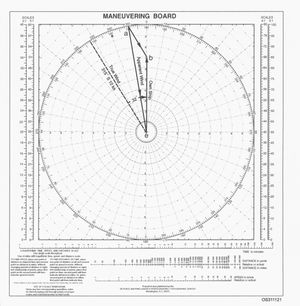
Along with the dead reckoning tracer the “maneuvering board” would be the FDOs constant companion. The maneuvering board was a simple sheet of paper, usually about two feet across, with a polar coordinate grid printed on it and various scales along the sides and bottom. As simple as it was, it was very useful. With it, the FDO could not only plot the track of air targets but also solve problems in relative motion by use of vector algebra. For example, by plotting the locations of friendly fighter and an attacker, and then computing the attackers speed, he could compute the heading and speed needed by a friendly fighter to intercept the attacker. The board was just as useful in solving problems concerning the relative motion of surface ships. Of the maneuvering board, CAPT Hammond wrote, “Classes provided daily drills in the use of the maneuvering board which later aboard ship were used so extensively in response to an order from the OOD (officer of the deck), ‘Radar, give me a course and speed on that surface target and his CPA (closest point of approach)." This was usually followed in less than 30 seconds with, “Radar, what’s holding you up?” [25, p.7]
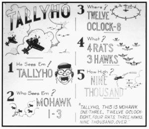
The School borrowed a lot of doctrine and procedures from the British. For example, no raid should come in unopposed because an attack by only a few defending fighters could be enough to disrupt a raid and ruin their coordination. Also, intercepts should be made as far out as possible, friendly fighters should be given an altitude advantage over the raiders, and friendlies should be brought in up-sun of the raid if possible. A reserve of defenders should always be positioned between the incoming raid and fleet center to be used against a possible next raid, and the FDO must be able to judge when additional fighters must be launched. The senior FDO or the Radar Plot officer was to assign a specific CAP and a specific raid to an assistant FDO who was to control the CAP until the fighter leader reported “tallyho” meaning he had the raid in sight. At this time the flight leader would take over directing the attack. The controlling FDO would be expected to keep his transmissions with the combat team to a minimum, but he must obtain and record the tallyho and “splash” reports. The students were taught that, in general, any unidentified aircraft detected by radar should be intercepted, and the FDO should not wait to get amplifying information; CAP should be vectored out immediately. This will give the defenders time to make more runs on the enemy. Furthermore, they were taught that fighters should stay joined up, as it was most effective to hit a raid simultaneously with one large group than to break the attack into smaller groups attacking in sequence. [25, p.9, p.15] [52, p.82, p.100, p.104-, p.106]
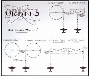
Sending orders to their tricycles, the student FDOs practiced different types of intercepts. They learned that if good altitude information was available the best way to have a large group of friendly fighters deal with a large raid was the “head-on intercept.” This was especially true if the skies were cluttered with a number of nearby friendlies. It would be best if the intercept were not exactly head-on, but rather the CAP should be slightly offset so that they first see the bogey at an eleven o’clock or one o’clock position. Next, the ‘controlled intercept’ could be very effective if the radar picture was up to date and the skies were relatively uncluttered. It was imperative with the controlled intercept that the controller know fairly precisely where CAP and bogey were at all times, because the FDO was going to guide the flight in the same manner as the flight leader would, if he could see the bogey. His goal was to get the fighters in a position well above the enemy, on the same heading as the enemy, and with the bogey behind him in a five or seven o’clock position. At tallyho, the CAP would peel off and dive on the bogey. The Fighter Director’s Manual stated, “A successful controlled interception requires a large degree of skill, and should not be attempted by an inexperienced controller.”
The third type of intercept was the “orbit and wait” where the controller brought his CAP out to a point ahead of the raid where they could lay in wait. The future FDOs were taught that the head-on intercept was usually the most effective, but there were a number of conditions where orbits could be used to advantage, most of them being related to deteriorated radar conditions.
The Fighter Director’s Manual states, “..... controllers must get their messages across and at the same time instill confidence in those under their control. Clear positive transmissions are mandatory.” To ensure clearness and preciseness of meaning in radio transmissions between CAP and controller, the US Navy adopted the British fighter direction glossary almost verbatim. Following are some examples:
- Altitudes
- Altitude - Altitude of enemy aircraft in feet
- Angels - Altitude of friendly aircraft in thousands of feet
- Speeds
- Saunter - Use maximum endurance speed
- Liner - Use maximum cruising range speed
- Buster - Use maximum sustained power
- Gate - Use maximum possible power - for a limited time
- Vectors
- Vector - Change heading to a magnetic heading given in a three-figure group
- Steer - A magnetic homing course given in a three-figure group
- Aircraft types [not inclusive]
- Bogey - Unidentified aircraft, possibly a friendly
- Bandit - Confirmed enemy aircraft
- Boxcars - Heavy bomber
- Fishes - Torpedo planes
- Shads - Shadower patrol aircraft
- Weather
- Pillow - Visibility in miles
- Quilt - Height of top of cloud layer in thousands of feet
- Mattress - Bottom of cloud layer in thousands of feet
- Aircraft Status
- Ammo Minus - Less than half ammunition left
- Ammo Plus - More than half ammunition left
- Ammo Zero - Out of ammunition
- What State? - Report fuel and ammunition remaining
- Pancake-Land - Coming back short of ammunition, wish to land
- Pancake-Hurt - Coming back wounded or damaged, wish to land
- Engagement Status
- Splashed - Enemy aircraft downed, followed by number and type
- Grand Slam - All enemy aircraft engaged have been shot down
- Standard Transmissions
- Affirmative - Yes, correct in answer to a question
- Roger - Have received all of your last transmission
- Wilco - Have received and understand last transmission and will comply
- Emergency Transmissions
- Skit It - Do not attack
- Salvoes - Am about to commence AA fire
- Heads Up - Enemy got past me
- Hey Rube - Need support
In their many hours of practice intercepts, the students learned standard voice radio procedures. The Fighter Director’s Manual noted, “Correct R/T is the only basis for efficient voice communications, and its importance cannot be overemphasized. All officers and men whose duties involve the use of radio-telephone must know and adhere to the standard procedure.” The procedure called for the following:
- The voice must be kept natural. Doing so denotes calmness and is normally more understandable.
- Before you speak have your message already formulated. Be authoritative when you do speak.
- Always finish a message, never break off. Confidence is lost in broken transmissions.
- Before you speak, listen. Wait a few seconds after another controller or pilot has spoken.
- Keep messages brief.
[52, pp.29-32, pp.34-40]
To summarize what the future FDOs were expected to be able to do, the Fighter Directors Manual stated, “The controller must bring to his task an alert mind and be capable of quick action based on sound and rapid judgment. The requisite skills can be developed only through long and arduous practice. But such skills are vital, for effective control of aircraft can mean the salvation of an operation, its misuse may mean the destruction of the fleet.” A skilled FDO was expected to be able to control three formations of fighters simultaneously. [57, Promulgating letter] [25, p.10]
The Graduating Class
During their days under instruction, the San Diego student FDOs from time-to-time questioned “Why me?” or “Why us.” They had all been picked for the same class at the Northwestern University Midshipmen’s School, and they wondered, did they have something in common that caused the Navy to select them for fighter direction, or had the Navy just arbitrarily decided to send the whole class to FD school. They searched for a few common denominators in their backgrounds. Most had college degrees, but their schools ranged from Ivy League to small community colleges. Many had lettered in college sports, but others were far from being athletes. Some had studied science and engineering, but others were English and political science majors. A few wore glasses while studying, but none wore glasses all the time. Aside from three from New York state and two from Missouri, all were from different states covering the extent of the USA. Analysis showed no common denominator. Years later, three of the students tried to compile a list of the twenty-five ensigns who started the course. To the best of their memories they were able to recall fifteen of the students and their two instructors. It was a diversified group as follows:
| NAME | HOME STATE | SCHOOL |
|---|---|---|
| CO LCDR Jack Griffin | Colorado | U.S. Naval Academy |
| XO LTJG Henry Rowe | Texas | U.S. Naval Academy |
| ENS Richard Casper | Unknown | Unknown |
| ENS Victor England | Oklahoma | University of Oklahoma |
| ENS H. Stanwood Foote | Missouri | Westminster College |
| ENS Garvin Hale | Kansas | University of Kansas |
| ENS Nicholas J. Hammond | California | Fresno State College |
| ENS Jack Hampton | Iowa | Unknown |
| ENS Stewart Henslee | Tennessee | University of Tennessee |
| ENS Louis Kahn | Texas | Texas Mines College |
| ENS Hal Long | Wisconsin | Compton Jr. College |
| ENS Charles D. Ridgway, III | New York | Princeton University |
| ENS Bruce Selkirk | Missouri | Unknown |
| ENS Landon Thorne | New York | Harvard University |
| ENS Pat Trench | Illinois | Illinois Technical |
| ENS Tom Ward | New York | Williams College |
| ENS Tom Young | Washington | University of Washington |
Twenty-two out of the twenty-five graduated, and all were sent to radar equipped ships. Those with the highest grades were sent to aircraft carriers, however, one of those sent to carriers was assigned to the gunnery department and never served in Radar Plot. As the years went by, at least three of the graduates would rise to Task Force or Task Group fighter director officers; an awesome job for a relatively junior officer. Navy personnel managers would eventually learn there were some definable characteristics that made for a successful FDO. More about this later. [25, pp.3-5]
Click here to go to “The CXAM Goes to War - Chapter 6 of Radar and the Fighter Directors.”
