Ohio Brass High Voltage Laboratories
This article was initially published in Today's Engineer on April 2014
Increased transmission voltages in overhead wires, which rose from 25 kV in 1891 to 220 kV by the early 1920s, required electrical engineers to develop tools for testing the equipment used in high-voltage lines. What exactly did happen to electric lines under storm conditions? How much might rain, fog, or snow reduce an insulator’s dielectric strength? Phenomena such as corona and power loss also needed to be understood. The study of insulation materials was still relatively new, and it was becoming clear that the longer lines with their higher voltages required advanced designs. As J. T Lusigan and H. L. Rorden, both of the Ohio Brass company observed in a later paper, “The need for ample electrical clearances, particularly for full-sized tower and equipment dictates that some provision for outdoor studies be made.”
Much of what the world knew about high-tension insulators in the twentieth century was learned at the four high-voltage laboratories established by the Ohio Insulator Company (which later changed its name to Ohio Brass Company). The first laboratory was established in 1910, while laboratory number four is still operating.
Of the four laboratories, number two (1926-1933) was the most visually striking, a juxtaposition of Victorian elegance and high-tech equipment on the former estate of O. C. Barber, who had made his fortune manufacturing matches, and for whom the town of Barberton, Ohio was named. Barber died in 1920, but it took until 1926 to settle his estate. In 1926, Arthur Oswin Austin (an AIEE and an IRE Fellow) purchased a large tract of land, the mansion, and the horse and colt barns belonging to the estate. The Ohio Insulator Company had ordered four 2200 volt to 600 kilovolt 60-hertz test transformers from the Allis-Chalmers company at about this time. Austin found he could over excite the iron cores of the transformers to obtain a new rated average of 2750 volts to 750 kilovolts. A synchronous switch was used to produce either a positive or negative transient overvoltage to spark over the sphere gap and apply the capacitor voltage to the specimen being tested.
Austin began testing with high-voltage impulse waves generated by charging a large screen wire conductor with the transformer bank and discharging it onto the test specimen. Austin's paper entitled "A Laboratory for Making Lightning" presented in Paris, France on 6 June 1929, shows the fourth transformer installed in the indoor test lab at the Ohio Insulator plant in Barberton, Ohio. Austin states that test voltages up to 900 kV were generated.
A.O. Austin (1879-1964) was credited with thirty-four inventions or major developments. The "cap and pin" suspension insulators used in the construction of a 110 kilovolt power transmission line built in 1909 from Niagara Falls to Ontario were his invention. Much of the data used in developing methods of protecting aircraft from lightning strikes came from experiments conducted at the High Voltage Outdoor Laboratory at his farm.
By 1933, the laboratory needed space for even more powerful equipment, including a 3,000 kV Marx impulse generator, and a new laboratory was built adjacent to the Ohio Brass factory in Barberton, Ohio.
Laboratory Number One -- 1910 to 1926
The first laboratory was located in Building 3 at the Ohio Insulator Plant at Park & 9th Streets in Barberton, Ohio. The principle test voltages used at this time were generated by Tesla coils with a frequency from 20 kilohertz to 70 kilohertz because the exact wave shape of lightning was unknown.
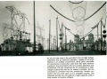
The first photo shows a 12-unit suspension insulator string in a mock tower setting with insulated horns at the bottom of the string and an expanded cage over the conductor. The 630 kv 60 kilohz high-voltage rain test flashes the end of the unshielded conductor 4.57 meters to the floor. The 1.5 m insulator string with insulated horns and expanded conductor withstands the test wave.
The second photo shows a needle gap in the lower left, seen in parallel with a sphere gap in the lower right with both gaps approximately equal in length and both flashing over from high frequency high voltage. The "air core transformer" may be a Tesla coil immersed in the oil tank shown in the center of the picture with a high voltage bushing mounted on top. The slender column shown in front of the oil tank apparently contains the high-voltage resistor. When the sphere on top of the bushing flashes over to the sphere mounted on top of the resistor column, both the parallel needle gap and the sphere gap are shown flashing over.
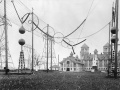
The third photo photo shows the outdoor Ohio Insulator Company's high voltage testing laboratory in Barberton, Ohio. It is shown in Figure 4 of A. O. Austin's June 16, 1925 paper titled "Present use of insulated controls for reducing the number of arcs to ground on transmission lines" presented in Paris, France. This laboratory was located outside Bldg. 3 at the Ohio Insulator manufacturing plant at Park and 9th St. in barberton, Ohio. A. O. Austin conducted most of his high voltage tests at this time using high frequency (10 kilohz to 70 kilohz) voltage generated by Tesla coils as shown in the center of the photo. The top of a transmission tower with a 7 unit suspension insulator string is shown on the right. The function of the two large corrugated silos, one located on the left and one on the right behind the Tesla coil, is uncertain.
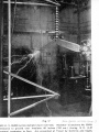
Rain test at the Ohio Insulator high voltage test lab #1 at Park & 9th St., Barberton, OH, 1923
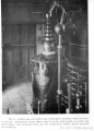
Indoor test and flashover of needle and sphere gaps at the Ohio Insulator high voltage test lab #1 at Park & 9th St., Barberton, OH, 1923. A 12-unit suspension insulator string in a mock tower setting with insulated horns at the bottom of the string and an expanded cage over the conductor. The 630 kv 60 kilohz high-voltage rain test flashes the end of the unshielded conductor 4.57 meters to the floor. The 1.5 m insulator string with insulated horns and expanded conductor withstands the test wave
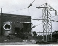
Ohio Insulator Company's outdoor high voltage testing laboratory in Barberton, Ohio, 1925


Laboratory Number Two -- 1927 to 1933
O. C. Barber, who had made his fortune manufacturing matches, and for whom the town of Barberton was named, died in 1920, but it took until 1926 to settle his estate. In 1926, Arthur Oswin Austin purchased a large tract of land, the mansion, and the horse barn belonging to the estate. The Ohio Insulator Company at about this time (1926-1928) had ordered four 2200 volt to 600 kilovolt 60 hertz test transformers from the Allis-Chalmers company. A. O. Austin found he could over excite the iron cores of the transformers to obtain a new rated average of 2750 volts to 750 kilovolts. A. O. Austin began testing with high-voltage impulse waves generated by charging a large screen wire conductor with the transformer bank and discharging it onto the test specimen. Figure 30 of A. O. Austin's paper entitled "A Laboratory for Making Lightning" presented in Paris, France on 6 June 1929 shows the fourth transformer installed in the Building 3 indoor test lab at the Ohio Insulator plant in Barberton, Ohio. A. O. Austin states that test voltages up to 900 kv were generated.
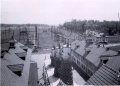
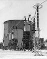
Ohio Insulator high voltage test lab #2 located on the estate of Arthur Oswin Austin, Ohio Brass Company, Barberton, OH, 1929. This photo shows the colt barn on the right with two vintage automobiles parked in front. The three high-voltage test transformers are rated 750 kv 500 kva each. One 150 cm sphere gap is shown to the left of the wire cage conductor and one 150 cm sphere gap is shown on the right of the wire cage conductor. The right sphere gap (west) has the smaller gap indicating that the test specimen was one of the towers shown on the right
Three 750 kv test transformers are shown in the bay of the ornate horse barn. Barberton, Ohio, 1929
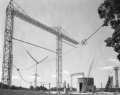
Ohio Insulator Company's outdoor high voltage testing laboratory in Barberton, Ohio, 1929
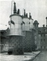
Three test transformers in the center bay of the horse barn. Barberton, Ohio, 1929
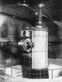
Ohio Brass. Large transformer for normal frequency tests up to 900 K. V. to ground.


Laboratory Number Three -- 1934 to 1968

A. O. Austin retired in 1933, and the lower two transformers at the horse barn were moved to the new outdoor high voltage laboratory being constructed adjacent to the Ohio Brass factory in Barberton, Ohio. The indoor transformer could be connected in series with the two outdoor transformers by means of a high-voltage roof bushing. A September 1934 AIEE paper in Electrical Engineering, "A New Laboratory for High Voltage Testing" by J. T. Lusignan and H. L. Rorden describes the new outdoor and indoor laboratories at this site. A new 3000 kv MARX impulse generator was constructed for use in both the indoor and outdoor lab. In about 1960, a new outdoor 4000 kv impulse generator was constructed and many improvements were made. In 1967, high voltage design tests were performed for a proposed 765 kv transmission system for American Electric Power.
Laboratory Number Four -- 1968 to Present
The new outdoor testing laboratory at the F. B. Black Research Center opened in the summer of 1968. The high-voltage bushings on the three transformers were replaced with modern Ohio Brass condenser bushings. The insulated pedestals on which these transformers were mounted consisted of porcelain station post insulators. The 4000 kv impulse generator in Barberton was moved to the new lab in Wadsworth, Ohio, and a new 1000 kv addition was made. This 5000 kv impulse generator with its 3000 kv capacitor voltage divider was used to perform switching surge tests on the proposed 1500 kv double V-string in the large portal tower for American Electric Power.
Three 750 kv test transformers mounted on top of their porcelain post pedestals.
Ohio Brass outdoor high voltage testing lab located northwest of Wadsworth, Ohio.


The IEEE History Center gratefully acknowledges the materials and assistance given by John F. Wiitibschlager, High Voltage Lab Manager 1963-1993, in writing this article
Further Reading
"A New Laboratory for High Voltage Testing" by J. T. Lusignan and H. L. Rorden