First-Hand:The Beginnings of Force-Feedback: A Memoir
Submitted by A. Michael Noll
February 4, 2022
© 2022 AMN
Abstract
In the late 1960s, a three-dimensional force-feedback system was designed and constructed at Bell Labs – what today would be known as haptics and virtual reality. This system was implemented and constructed, finishing in 1970, at Bell Telephone Laboratories, Inc. in Murray Hill, NJ, where I was employed as a Member of Technical Staff in the Communication Sciences research division. This article summarizes the invention of force-feedback for computer output, and reviews its documentation.
The Idea Forms
In the later 1960s, Maurice Constant visited Bell Labs, and I attended a presentation that he made there. His comments stimulated me to design and make a three-dimensional force-feedback system. Constant was affiliated with the National Film Board of Canada and was speaking at Bell Labs in a conference room. I remember sitting toward the rear. He challenged us to make some sort of system so that an artist could communicate with the computer using hands to shape some sort of virtual clay. He stimulated me to design and make a three-dimensional force-feedback system that would fulfill his vision.
3D Input Device and Stereoscopic Displays
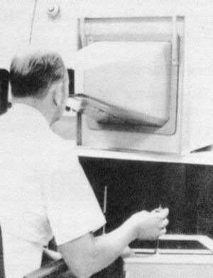
At Bell Labs, I was previously doing 3D stereoscopic computer animation. Peter Denes had installed an interactive laboratory computer system, mostly for speech research, consisting of a Honeywell (Computer Control Company) DDP-224 computer. With the help of Charles Matke (a mechanical wizard at Bell Labs), we designed stereoscopic displays for this interactive system, along with a 3D joystick device for the input of rectangular coordinates.[1] A user could draw in a 3D space, using the software I had programmed and the 3D joystick. The joystick moved in a space of about one cubic foot. The z-axis was balanced so that the joystick would remain in place when the user no longer touched it. We later made an improved version, in a red enclosure, of the 3D input device. Along with the 3D display, drawing in interactive three dimensions was possible.
The interactive DDP-224 computer system had an interactive CRT display, mostly of vector graphics. It also had various input devices, such as a little box with knobs and switches that we had designed. It had a pen and tablet for graphics, but the pen lost its position when it was placed down.
The Tactile Device
Maurice’ Constant’s challenge gave me the idea to motorize the 3D input device so that the motors would create forces to impede the movement of the 3D joystick in the x-y-z directions. That would then create forces to create force feedback and make a tactile communication device for use as output from a computer, along with 3D input.
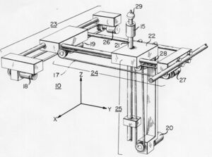
My specifications for the hardware for the tactile device were that it operates within a cubic foot, have no deflections, and be able to exert a force of about 12 pounds in all three directions. I decided on rectangular coordinates, similar to my 3D input device.
The objective was a tactile device that not only simulated shapes and surfaces but also weights and mass. Hydraulics were considered, but abandoned because of concerns over fluid leaks around computer – also over them being somewhat slow. Thus a mechanical device with electrical motors operating in rectangular x-y-z coordinates was decided upon.
When fully extended, deflection had to be no more than 0.015 inches under a maximum force of 12 pounds. The rods thus had to be one-inch in diameter to minimize deflection to satisfy this design requirement. One-inch diameter casehardened steel rods were used to eliminate any bending. The rod for the vertical z-direction had to be hollowed to minimize its weight. The machine shop at Bell Labs went through a number of rods in the process of drilling them out: rods deformed and shattered. But finally, success was achieved.
Linear bearings were used to minimize friction and any spurious movement. Two-phase 60 Hz 10-watt, reversible, induction motors were used to resist or assist movement. Chains with links connected the motors to the rods, with sprockets. Linear potentiometers sensed position. The outputs of three digital-to-analogue convertors were connected by relays to multipliers used to control the three motors.
A metal ball at the top of the z-axis rod was split in half as a safety measure. The user’s fingers had to bridge the two halves to supply input to the motors. We attempted to construct a three-dimensional strain gauge to measure the force directly between the user’s hand and the metal ball to the top of the vertical rod. However, we were unable to get it to work reliably.
The device was connected to the computer. The potentiometers gave position, and the output from the computer controlled the motors to give force. The initial implementation with software to control the device resulted in much chatter in simulating a solid surface. Some control theory had to be used to eliminate any chatter and assure smooth simulation of solid surfaces.
The device was used simultaneously with a 3D stereoscopic display so that users could both feel and see objects – or just feel them without any display. Shapes and surfaces were simulated.
After my system was implemented, I heard of research, which I believe was at the University of California at San Diego, to construct a force-feedback system utilizing cables. I felt there would be much stretch and bounce in such an implementation. I also learned of a two-dimensional device to give a sense of feel for molecular study, proposed by Fred Brooks of the University of North Carolina in 1971.[2]
Patent, Publication, Applications
Although the construction and testing of the tactile system was completed in 1970, publication had to wait for the patent attorney at Bell Labs to finish the writing of the application for a patent. This patent filing was complicated by the device being the subject of my doctoral dissertation at the Polytechnic Institute of Brooklyn. Brooklyn Poly agreed that the device could be both the subject of my dissertation and remain the intellectual property of Bell Labs. Once the patent application had been submitted, my dissertation was submitted to Brooklyn Poly for final approval by my dissertation committee.[3]
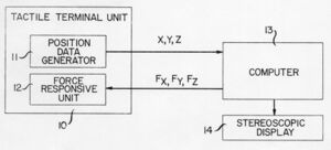
The overall drawing on the front page of the patent showed a Tactile Terminal Unit (with a Position Data Generator and a Force Responsive Unit); a Computer; and a Stereoscopic Display.[4] This broad drawing and associated claims in the patent would seem to cover much of what today are called “virtual reality” and haptics.
Back then in the early 1970s, there was no ACM SIGGRAPH, and thus there was no really appropriate journal in which to publish a paper about the tactile communication. So I chose the Journal of the Society for Information Display. Today there is even a IEEE Journal on Haptics and even an International Society for Haptics. Back then, in the late 1960s, the term “haptics” was not yet discovered, and I used such terms as “force-feedback,” “tactical communication,” and “Feelies” to characterize my research. The paper was ultimately published in the Journal of the Society for Information Display in 1972.[5] The opening to the paper stated: “With a three-dimensional … tactile device, you can ‘feel’ a three-dimensional object which exists only in the memory of the computer.”
The paper suggested the use of tactile communication for the visually impaired – the blind. The ball was like the stick used by a blind person, as if a grasped pencil being used to poke and explore. A visually impaired person could feel a curve or a complex surface, and even objects.
The depiction of surfaces was challenging in the early days of computer graphics. Grid lines were drawn on surfaces, or dots scattered at random. This took much computing power. A stereoscopic 3D display helped much. But simply feeling a single point on a surface and being able to move that point all over the surface did not require much computing power and gave a real “feel” for the shape of the surface.
Telecommunication of touch over distance was also described in the paper, in which hearing, vision, and touch could be telecommunicated over distance – a form of “teleportation through telecommunication.”[6]
Next Steps
I recognized that this device was a first- generation approach and that improved models would follow. I wanted to replace the ball with some sort of means for the fingers to feel and grasp virtual objects. I also wanted to use the tactile device for research into psychological investigations. I envisioned using the tactile device with a head-mounted stereoscopic display (invented by Hugh Upton of Bell Helicopter),[7] with gimbals to sense position, and half-silvered mirrors so that the computer-generated imagery could be superimposed on reality.
As is the case sometimes with doctoral dissertations, the graduate becomes overly exhausted from the research and the writing of the dissertation – and looks for something new. In my case, I was given an opportunity in 1971 to join the staff of the White House Science Advisor – and left Bell Labs for Washington. I did not return to tactile communication.
Today, there are avenues of development of 3D systems: input and output, including tactile. Some sort of small 3D input device would be enable 3D drawing and input of data. Electromechanical design and innovation are still needed, even in today’s world of everything virtual and software defined.
Credits
As is usual for an involved engineering project, a number of people were involved. The force-feedback system I invented in the late 1960s was constructed by the mechanical and electrical geniuses at Bell Labs. They clearly deserve credit for the impossible that they made real.
D. Jack MacLean, Jr. designed the electronic circuitry for the device; Ronald C. Lupton and Charles F. Liebler of the drafting department prepared engineering drawings; and machinist Frederick W. Phelps, under the supervision of Karl H. Schunke, constructed the tactile device. John J. Dubnowski designed the circuitry for a dual CRT stereoscope; and Ozzie C. Jensen and Barbara E. Caspers were responsible for the hardware interface and associated software for the DDP-224 computer system. Peter B. Denes was responsible for the overall DDP-224 computer installation.
Charles F. Matke, who also designed initial models of the three-dimensional input device, designed a 3D strain gauge. Man Mohan Sondhi assisted in the intricacies of control theory and feedback design. Alfred E. Hirsch, Jr. prepared the patent application.
I express my gratitude to my thesis advisor, Prof. Ludwig Braun, Jr., at the Polytechnic Institute of Brooklyn for his belief and acceptance of this project as a doctoral thesis on “Man-Machine Tactile Communication.” The other members of my dissertation guidance committee were Profs. Clifford W. Marshall, Leonard G. Shaw, and Donald B. Scarl. My Doctor of Philosophy (Electrical Engineering) was awarded in June 1971.
Discussion: Haptics Today
There are people who believe that the earliest force-feedback systems were made in the 1980s, in ignorance of the work at Bell Labs in 1970. The term “virtual reality” was coined years after our research at Bell Labs, and the term “haptics” was not used when our research was done. The patent that was awarded in 1975 for our invention broadly divulges an overall system that covers most of the haptics and virtual reality of today. Scientific and technological progress builds on past work, but it seems that our work in tactile communication was done so early that it has escaped the timeframe of prior knowledge.[8]
The world applauds Google for making a cardboard 3D stereoscopic viewer, when 3D viewers were available over a half-century ago. Head-mounted displays are applauded as innovative, but the work in the 1960s by Hugh Upton at Bell Helicopter seems mostly forgotten.
Yet, a recent book by David Parisi does carefully document the work in force-feedback that we did at Bell Labs.[9] His book also documents the work around 1970 being done by others, such as Fred Brooks at the University of North Carolina. The use of remote manipulators is nicely described, although these manipulators were far too spongy at the time to be used for tactile communication with a computer. His book positions touch communication with computers within the much broader world of touch communication in general.
References
- ↑ Noll, A. Michael, “Real-Time Interactive Stereoscopy,” SID Journal (The Official Journal of the Society for Information Display), Vol. 1, No. 3, (September/October 1972), pp. 14-22.
- ↑ Batter, James J. & Frederick P. Brooks, Jr., “GROPE I: A Computer Display to the Sense of Feel,” University of North Carolina, 1970.
- ↑ Noll, A. Michael, “Man-Machine Tactile Communication,” Dissertation for the Degree of Doctor of Philosophy (Electrical Engineering), Polytechnic Institute of Brooklyn, May 24, 1971, University Microfilms (Ann Arbor, Michigan).
- ↑ United States Patent 3,919,691 TACTILE MAN-MACHINE COMMUNICATION SYSTEM (Filed: May 26, 1971; Issued November 11, 1975); Inventor: A. Michael Noll; Assignee: Bell Telephone Laboratories, Incorporated.
- ↑ Noll, A. Michael, “Man-Machine Tactile Communication,” Journal of the Society for Information, Vol. 1, No. 2 (July/August 1972), pp. 5-11.
- ↑ Noll, A. Michael, “Teleportation Through Communication,” IEEE Transactions on Systems, Man and Cybernetics Vol. SMC-6, No. 11, (November 1976), pp. 753-756.
- ↑ Upton, Hubert W., “Head-Mounted Displays in Helicopter Operations,” USAECOM-AAA-ION Technical Symposium on Navigation and Positioning, US Army Electronics command, Fort Monmouth, NJ, September 23-25, 1969.
- ↑ Archival documentation, including copies of the patent, the SID paper, and media coverage from the 1970s, is at the Poly Archive at the NYU Bern Dibner Library of Science and Technology.
- ↑ David Parisi, Archaeologies of Touch, University of Minnesota Press, 2018.


