First-Hand:Spanning the Cold War Nuclear Weapons Era: 1956-58 to 1994-2001
Spanning the Cold War Nuclear Weapons Era: 1956-58 to 1994-2001 - Introduction
Submitted by Roy Merrill, Senior Life Member
Winston Churchill made his now famous "Iron Curtain" speech at Westminster College, Fulton, Mo., on March 5, 1946, an event that many have seen as the symbolic inauguration of the Cold War. The ’50’s decade started with the Soviets exploding their first Hydrogen Bomb August 1953.
My engineering career started at Sandia Corporation in 1956-1958. During that time I developed a Nuclear Weapon safe & arm switch. It was a passive integrating accelerometer that was eventually incorporated into several thousand special weapons adaption kits in stockpiled nuclear weapon’s. This device was designed so that even after years of maintenance free storage, it would operate reliably to arm the weapon only after it experienced an acceleration profile resulting from being released midway through a high speed nose up and over maneuver by the delivering aircraft. This maneuver would toss the weapon into a parabolic trajectory to the target while the aircraft sped away in the opposite direction. (See Chapter 1.)
The end of the cold war occurred with the dissolution of the Soviet Union, a gradual process that took place from about 19 January 1990 to 31 December 1991. START (for Strategic Arms Reduction Treaty) was a bilateral treaty between the United States of America and the Union of Soviet Socialist Republics (USSR) on the Reduction and Limitation of Strategic Offensive Arms. The treaty was signed on 31 July 1991 and entered into force on 5 December 1994 under the Russian regime.
In the 1994-2001 interval, at Lawrence Livermore National Laboratory, I worked on two projects involved with reducing the U.S. nuclear weapons stockpile: developing the prototype for a simple, flexible device for disassembly nuclear weapon pits described in Chapter 2; and developing the supervisory process and robot program controls for a plant prototypic system for immobilizing waste Plutonium described in Chapter 3.
Chapter 1 - My First Professional Job: Developing a Nuclear Weapon Safe & Arm Switch; 1956-1958
Sandia Corporation in Albuquerque, New Mexico gambled that even though I had a commitment with the Air Force to begin in one or so years, I might make some worth while contribution before leaving. To travel to Sandia my wife, Ina, and I left the University of Idaho in mid-June 1956 following graduation for a leisurely drive, and car camping trip west along the Columbia River, then south down the Pacific coast in Oregon & California to Downey then east through Grand Canyon National Park on to Albuquerque. That vacation was memorable more for the time it took me to unwind and realize that college undergraduate studies were over and I could relax and enjoy the grand sights & people we visited along the way.
This new job was completely different from any I’d had before. My first office was in a "bull pen" of some 20 engineers. The hubbub could be very distracting especially when my neighbor, who was partially deaf, was on long distance calls. Despite that little problem, I soon felt quite comfortable with my new boss, Howard Devaney, and project mentor, Don Weems. Both were easy to know, and despite Don's jealousy of not having Howard's job, it was a great working environment. Howard gave me a task right off the bat to come up with a reliable means of integrating forward acceleration to a specific velocity change before closing an electrical switch. The objective was to design a safe & arm (S&A) integrating accelerometer for a special weapon ( nuclear bomb) adaption kit that would assist in arming the device only after it had experience a certain change in forward velocity. This change would only occur under specific weapon delivery scenarios.
I spent some time chatting with others in Howard's group who were working on the technical aspects of weapon S&A problems. Don was a good engineer and knew how to get things done; specifically, machine shop orders, environment test scheduling, and connecting with the mechanical technicians, expeditor, and other people with useful technical expertise. My assignment was not as easy as I had at first imagined. There were dash-cups, fans, clock movements, eddy-current devices, and other energy absorbers, but none possessing the passive principle which would allow either a linear or circular displacement rate proportional to the inertial force imposed (that is, an integrating acceleration) as a direct consequence of the applied acceleration. There was, however, one mechanism that kept coming up in my search. It was an escapement, a clock timing mechanism which, unfortunately, exhibited the displacement rate property proportional to the square root of the inertial force. It was a small device, and a rugged one also because it had been engineered over a number of years for these properties for use in numerous special weapons adaption kit S&A timer applications. But how could it be used effectively in solving this problem? With Don, we brain-stormed a dozen or so ideas that might have worked, but all were ruled-out for one reason or another.
After several weeks of studying the problem, I had about given up on the timer mechanism approach. It was then one morning while Don & I were exchanging ideas over a cup of coffee that I was suddenly struck by an interesting idea. I was so delighted with the thought, I snapped my fingers in a sudden downward motion. To my utter astonishment, Don jumped back and took a swing at me which fortunately Don checked in mid-stride. "What's going on Don?" I asked excitedly. Don explained that during action as an infantryman in the Korean War, he had developed an involuntary reaction to this type of sudden movement. We both laughed as I explained how one might be able to design a driving mechanism that would exhibit a piece-wise linear approximation to the proportionality property demanded in the design requirements.
Applying engineering methodology to this problem resulted in an innovation approach: bisect the inertial mass; link one segment directly to a sliding rack that meshed with a pinion on the clock escapement shaft; and link the second segment to a sleeve on the same rails, but behind the sliding rack and constrained by a constant force (Negator) spring. This inertial mass then could move and contribute to the force driving the escapement only when experiencing acceleration applied along the rails that exceeded a specific threshold level. The necessary mass of the second segment with respect to the first segment, and the corresponding force of the Negator spring were then chosen to achieve the required linearity over the range dictated by the maximum expected acceleration. It was a solid idea, and one that, after additional design work and comprehensive environmental testing, turned out to be exactly what the Special Weapons System Engineers needed.
I was called into active duty and assigned to the Air Force Wright Air Development Command just 18 months after joining Sandia, and one month after completing the operational acceptance testing of the S & A switch. After some 40 years, an old friend I worked with at Sandia told me this switch had been incorporated into over 2,000 nuclear weapons stockpiled as part of the USA deterrent in the cold war with the Soviet Union.
Chapter 2 - Remotely Operable Chip-less Pit Bisector: 1994-1995
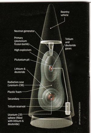
As a part of the Nuclear Weapons Disarmament Treaty, Lawrence Livermore Nat. Lab joined with other DOE Nuclear Weapons Labs in the late 1990's to develop ARIES, a weapons disassembly facility. (See the APPENDIX) My assignment was to design and develop a prototype machine for bisecting plutonium warhead pits that could be loaded by robot remotely in a glovebox, bisected without generating chips or fines(dust), and the parts unloaded by robot. It was also to be designed to accept most, if not all, the differing Hydrogen Bomb warhead types in the U.S. stockpile.[1] The warhead (Plutonium) pit is the nuclear trigger of a nuclear weapon as shown below in the stylized diagram.
The design process began by first investigating the sizes, shapes, and materials of all the Hydrogen Bomb warhead types in the U.S. stockpile. Next, all the pit bisector machines that had been developed up to that time by the participating nuclear weapons facilities in Los Alamos, Livermore and Savannah River were investigated. From this survey, it was determined that none were capable of accepting the pit loaded by robot, nor provide adequate access for the robot to remove the bisected halves and accompanying internal parts; most could not bisect the pit without generating plutonium chips & dust during the disassembly procedure.
One exception to those investigated had some features which we used in our design; it was an LLNL model that used a clam shell shaped vacuum chuck with labyrinth seal for holding the pit at one pole of its principle axis with high vacuum while being rotated about that axis during the bisecting operation. It also used a mechanism borrowed from the standard plumber's copper pipe cutter that could be adapted for our purpose to bisect pits without generating chips or, for that matter, even plutonium dust ('finds') in the process. What that design as well as all the others did not include was a practical means of accommodating pits that regularly warped some from a perfect circular shape under the large forces produced during the bisecting process. Most used a rigid lathe-like means of holding the pit during the cutting operation.
With my crew comprising a mechanical drafter and designer, two plutonium handlers, Dave Hole, my expeditor and scrounger, and advise from Dr. Leonard Gray, the Lab Plutonium properties expert; all on a rather limited budget of about $100,000 and a 18 month schedule, we designed, built and tested a remotely operable chip-less pit bisector. We used results from cutter materials investigations by Don Fischer, a Defense Systems Division engineer, in selecting the optimal cutter wheel contour, material composition and work-hardened finish.
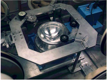
The final design consisted of a vacuum chuck with labyrinth rotating axis seal to sustain the vacuum while the pit was being bisected as shown in the next picture. It was designed so that the pit was held securely in place by the vacuum with a mechanism consisting of a three-point-suspension: the cutter wheel and two backup idler wheels all mounted on a rigid donut-shaped frame encircling the chucked pit. The axles of the three wheels were parallel with the vacuum chuck axis of rotation, and their yokes were attached to the frame at an approximate 135 degree arc from cutter to first idler, 90 degree arc idler to idler, and 135 degree arc idler back to cutter; and in a plane perpendicular to the vacuum chuck rotating axis as shown in the picture below:
(A fixture was devised for each pit type so that when mounted in the vacuum chuck with Labyrinth seal, it provided a matching mating surface to the pit contour, and elevated the pit’s major equatorial plane to be coplanar with that of the cutter & idler wheels. The cutting wheel was held in a lead-screw yoke assembly so that it could be advanced, or retracted on a line perpendicular to the pit surface and in the plane of the holding frame. The idler wheel axel yokes were rigidly attached to the frame. The idler wheel surfaces were composite rubber and crowned so they naturally tended to track the high point, or equatorial perimeter of the pit as it was turned by the rotating vacuum chuck.
The vacuum chuck was rotated through a speed reduction box by a high-torque variable speed ¾ hp induction motor powered by a variable frequency electrical power driver. The cutter lead-screw was driven by a high-torque slow-speed stepper motor. The frame holding the idler and cutter wheels was hinged so that with the cutter wheel retracted, it could be pivoted up and out of the way for robot access. The hinge mounted on a slider mechanism and attached to the bisector assembly had a slight unidirectional accommodation so that the whole subassembly could shift as needed while advancing the cutter wheel into the pit surface. This action in turn drew the idler wheels into contact with the pit producing a stable three-point suspension.
The idler wheel axles were securely attached to this frame with sufficient accommodation so that with the cutter wheel retracted and the frame in its' neutral position there was adequate clearance for the largest of the pit types. In this configuration, the frame could be safely hinged down into a mating restraint on the main bisector assembly. This restraint provided a reactive torque in response to the radial force transferred to the frame by the cutter wheel as it is advanced into the rotating pit and during the cutting operation. This cutting action could best be described as an extrusion process. To accomplish this bisecting process, up to 5 tons of force was exerted on the pit surface by the cutting wheel. Following the pit bisecting operation, and with the cutter wheel lead-screw fully retracted, the frame was hinged up out of the way so that a robot could reach directly in and retrieve the pit's bisected halves with associated internal parts and deposit them into a bag-out container. Once the pit parts had been removed, the bisector was ready to accept the next pit for disassembled.)
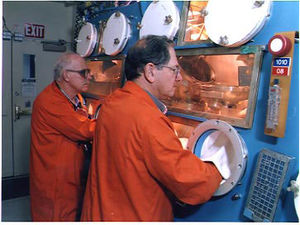
Throughout the acceptance tests in the LLNL Super-block Facility, the chip-less bisector operated in a glovebox by the Plutonium Handlers, successfully disassembled over 40 pits from a representative assortment of pit configurations withdrawn from the nuclear weapons stockpile. The details regarding shapes and sizes are restricted and cannot be divulged in this unclassified document.
This prototype proved the design and provided the necessary specifications for implementing the operational version used in the ARIES weapons disassembly facility. Its' picture was one of those featured in the Lab's pictorial history 18” x 30” poster of the R&D weapons work at Lawrence Livermore National Laboratory published in 1997.
The final design specifications for the remote chip-less bisector controller included a stored lookup table of the necessary lead-screw initial cutting positions, and the pit fixture rack and uncut pit rack locations. The vacuum chuck fixtures, and pits to be bisected were to be arranged in specific order in storage racks within the robot's reach.
(The control program was designed so that during normal operation, the operator need only enter the pit/weapon type to be bisected. Then with the cutter and idler wheel frame pivoted out of the way, the robot loaded the associated vacuum chuck fixture from its adjacent storage rack. To insure that the idler wheels and cutter wheel will be separated enough to allow unobstructed access to the mounted pit as the hinged cutter and idler wheel frame is lowered in to its operational position, the frame hinge mechanism was lightly sprung in both directions so that in the unloaded condition, it returns to its neutral position. Then, at completion of the pit loading operation and as the cutter wheel lead screw is advanced to the initial cutting position, the idler wheels drew up firmly in contact with the pit surface with the pit remaining centered & secure in the vacuum chuck. In this initial cutting position, the chucked pit's equatorial perimeter will be in line with, and tangent to, the idler and cutter wheel perimeters.)
Chapter 3 - Plutonium Immobilization Program: 1996-2001
From the publication of the 5 validation concepts for plutonium immobilization in the LLNL Science &Technology Review, April 1997 issue (See APPENDIX,) the development of an operational version of the #5 process so called “can-in-canister” approach validation plant prototype was authorized, and during the 1996-2001 time-frame was developed and successfully certified.
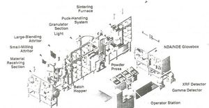
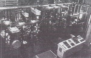
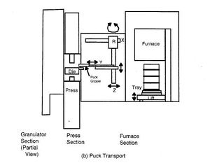
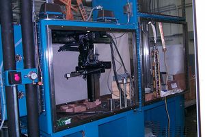
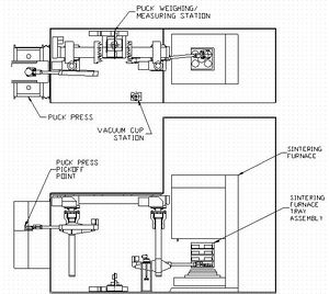
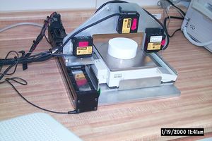
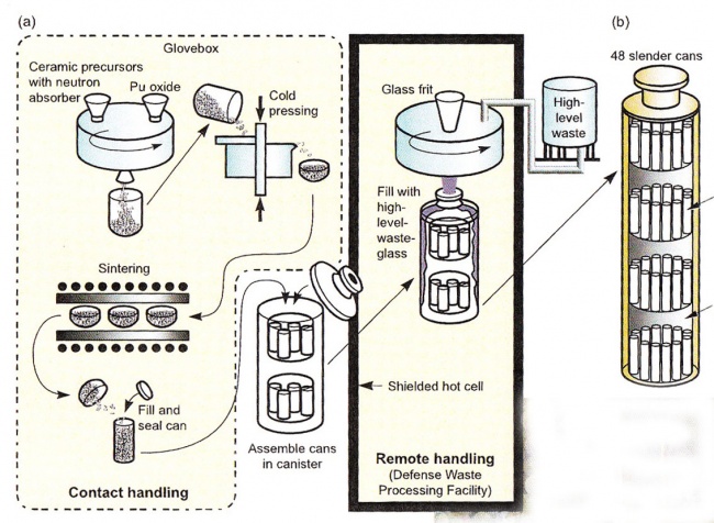
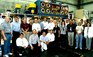
My assignment in the development of a plant prototypic system for immobilizing waste Plutonium (some 13 Tons) accumulated from the Nuclear Weapons development, production and disassembly programs, was to design and implement: (1) the plant processing stations operational system data acquisition and controls, and operator station controls; (2) the powder hopper two degree-of-freedom 5-stage linear robot program controls; (3) the compressed and sintered pellet/puck three degrees-of-freedom articulating robot program controls; and (4) complete the pellet size and weight measuring station. The ceramic form was made by blending plutonium oxide with ceramic precursor materials and a neutron absorber. The mixture was calcined, cold pressed, and sintered (furnace heated, but not melted) into a dense form, then loaded into small cans. In the operational version of this plant, these cans are to be placed inside a large storage canister and surrounded by glass made with highly radioactive waste, then stored in an underground repository. The PuCTF (Plutonium Ceramification Test Facility) is pictured below in schematic and photo image form followed by a photo of the project staff. The facility was housed in a 18 ft long x 3 ft wide x 12 ft high glovebox.
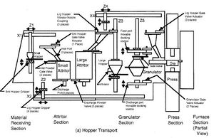
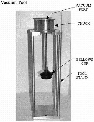
To accomplish the ceramification results described in the APPENDIX, the PuCTF System performed as follows: a linear 5-stage robot Hopper Transport System Z1-Z5 loads the powder hopper with bagged-in Pu and the ceramic ingredients with neutron absorber, gadolinium; transferred this powder into a small attritor; unloads the attritored powder after the milling operation and transfers it into the large attritor; unloads the attritored powder after the second milling operation and transfers it into the granulator; unloads the granulated powder after the granulating operation (before and after each of these loading and unloading operation, the hopper is weighed to be sure all powder has been unloaded, if not that operation is repeated and the operator alerted) and transfers it into the 60 Ton press powder reservoir; after a measured quantity is compressed into a green puck (this operation is repeated until all of the powder has been compressed), it is picked up and placed on the size and weight measuring station by the articulating robot; after the green puck is sized and weighed, it is picked up by the articulating robot and loaded in an ordered manner on to the shelves of the bottom loading furnace (this sequence of steps is repeated 24 times to fully load the furnace); when full, the bottom is raised closing the furnace, the pucks are sintered during a furnace heating and cooling cycle, then the furnace bottom is lowered; the articulating robot picks up the sintered pucks one by one from the furnace shelves, places each puck on the sizing and weighting station; then following the measuring process, places the pucks into a bag-out storage can using a puck pickup vacuum tool.
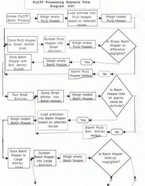
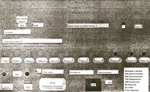
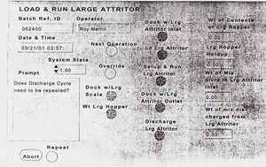
The Supervisory Control & Data Acquisition System was designed so that during the check-out and certification procedure, the operator at a console was able to interactively supervise each step/process, monitor its results, then if satisfactory, signal the operational supervisory control to execute the next process step. (See Roy D. Merrill, “In Support of the Plutonium Immobilization Program,” LLNL Report, April 12, 2001) The following examples taken from this report show the partial flow diagram of the logical steps taken in loading actinide, and processing it in the small and large attritors.
The puck robotic remote equipment for the PuCTF were developed by Kurt Peterson, and Don Pak; and the Author developed the robot control programs and the puck weighing & measuring station control programs. (See Don Pak & Roy Merrill, “Material Transport System in Support of the Plutonium Immobilization Program,” American Nuclear Society Ninth International Topical Meeting on Robotics & Remote Systems, Seattle, WA Mar. 4-8, 2001; and Kurt Peterson, Donald Pak & Roy Merrill, “Remote Equipment Development for the Plutonium Ceramification Test Facility at LLNL,” WSRC-MS-2000-00915, Rev. 1.) Kurt & Don were on loan to LLNL from Westinghouse Savannah River Co. during this project.
Appendix: Background For ARIES System Concept
(Extracted from LLNL’s Science & Technology Review, April 1997)
Tearing down the Berlin Wall in 1989 symbolized the end of the Cold War. However, the real work of ending the Cold War--sharply reducing the number of nuclear weapons--remains to be done. The governments of the United States and Russia have taken the first steps toward nuclear arms reduction by negotiating the Strategic Arms Reduction Treaties. Under START I, which was ratified in 1991, both countries agreed to reduce their large nuclear weapons arsenals to approximately 6,000 warheads and have already begun to do so by dismantling between 1,300 to 2,000 weapons each year. START II, when it is ratified, will reduce the numbers further to between 3,000 and 3,500. The dismantling of weapons and the cessation of new nuclear weapons manufacturing, while positive for world peace, have raised a problem: what to do about the fissile materials recovered from the weapons or in inventories that will remain unused. These materials--primarily plutonium and highly enriched uranium--are environmental, safety, and health concerns. But of more urgency is the threat they pose to national and international security if they fall into the hands of terrorists or rogue nations. As arms reduction continues and amounts of surplus fissile materials increase, the potential for such security breaches will increase. As part of bilateral nuclear nonproliferation work, both the U.S. and Russia have initiated scientific studies to find a way to dispose of surplus fissile materials.
In the U.S., the Department of Energy is the technical lead for the disposition studies, acting as a member of the Interagency Working Group of the White House Office of Science and Technology. In this capacity, DOE has mandated separate studies for disposing of plutonium and highly enriched uranium, because of their different chemical characteristics. Lawrence Livermore is focusing primarily on the study of plutonium disposition.
Plutonium Disposition
After a series of studies, including technical work for a preliminary environmental impact study, DOE selected three reasonable plutonium disposition alternatives for further study: using plutonium as reactor fuel; encasing it in other material, thereby immobilizing it and making it inaccessible; and burying it in a deep borehole. Lawrence Livermore is involved in studying the front-end processes required to prepare plutonium for disposition and is performing research and development on two of the three specific disposition methods to determine their viability. Specifically, Lawrence Livermore is working with Los Alamos National Laboratory on a system for disassembling weapon pits (or cores, where detonation takes place), recovering the plutonium in them, and converting it into a disposable form. Livermore has also led the two teams studying the immobilization alternative and the deep burial alternative. Oak Ridge National Laboratory is studying the reactor-fuel alternative. The Programmatic Environmental Impact Statement for plutonium disposition was published in December 1996. In January 1997, DOE announced its Record of Decision on plutonium disposition, recommending a dual disposition path: immobilize low-grade plutonium materials and use high-grade plutonium materials to fuel reactors. The alternative of burying surplus plutonium in a deep borehole ran into siting and licensing difficulties and was eliminated from consideration, despite the fact that Livermore studies proved it to be as technically feasible as the other two alternatives.
Recovery and Conversion
Lawrence Livermore and Los Alamo designed a plutonium recovery and conversion system called the Advanced Recovery and Integrated Extraction System (ARIES).
ARIES has five modules, which are used for: pit disassembly, converting plutonium into an oxide (for disposition), converting plutonium into a metal (for long-term storage), packaging plutonium for storage, and performing nondestructive assay to account for plutonium quantities. Lawrence Livermore is focusing on the first two modules.
The pit disassembly, ARIES' first module, consists of a glovebox in which the weapon pit is received; remote handling devices that transfer pits onto a scale for weighing and then move them on to be inspected and have any appurtenant devices removed; and a bisector that separates the pit into two half-shells by using a chip-less cutting wheel. The bisector framework remains stationary while the pit is rotated. The bisector design takes into account the dimensions, encapsulation methods, construction materials, and manufacturing techniques of these pits in order to incorporate the representative configurations that will be processed through ARIES. It also calls for a "no-hands-on" process to keep radiation exposures to the operator within acceptable limits. Bisector improvements are being made and will be tested during 1997.
Producing Plutonium Oxide
To be suitable for most of the disposition methods, plutonium must first be converted into plutonium oxide, the job of ARIES's second module. Lawrence Livermore has been developing pyro-chemical techniques to accomplish this conversion using various hydride/oxidation (HYDOX) reactions.
Three such processes are being researched, all based on reactions in which pure hydrogen gas is used to remove plutonium from a pit by forming a plutonium hydride. The formation of the hydride causes the plutonium to break up into small particles and separate from the other pit materials. The plutonium hydride is collected and then converted to plutonium oxide either directly or after conversion to plutonium nitride. The experiments on the HYDOX processes seek to minimize production cycle times and maintain safety while producing oxide particles to the required disposition specifications, particularly the more stringent specifications for oxide fuels used in reactors. A prototype HYDOX furnace has been designed, assembled, and installed and is being used to test the various process options. An additional unit is being assembled in a glovebox and will be installed and operated at Los Alamos as part of the ARIES demonstration.
The Spent Fuel Standard
Because most nations and even some terrorist groups are technically capable of converting surplus plutonium into nuclear weapons, the ideal disposition method eliminates the possibility of surplus plutonium being used for weapons. If a disposition method is not available within a reasonable time frame, the growing volume of plutonium surplus will make proliferation easier and render arms-reduction agreements meaningless. Because total elimination is not a practical objective, a National Academy of Sciences study, commissioned by DOE's Office of Nuclear Energy, proposed the next best thing: minimize accessibility. Dubbed the "spent fuel standard" and accepted as the goal of plutonium disposition efforts by the U.S., Russia, and the seven other stakeholder nations, it defines "minimized accessibility" as equivalent to the accessibility of the plutonium found in spent reactor fuel. The spent fuel standard is a reasonable goal because the technology to accomplish it appears achievable within 10 years and implementation can be completed within 25 years. It is also a practical goal because, by definition, it excludes spent fuel plutonium--which comprises the larger part of the surpluses--from disposition and concentrates on weapons-grade plutonium.
The Immobilization Task
Lawrence Livermore is researching plutonium immobilization with the Savannah River Technology Center, Argonne National Laboratory, and Pacific Northwest National Laboratory. Several U.S. universities and private industries are also partners, as are several other nations (including Australia, the United Kingdom, France, and Russia) with interest and experience in immobilization. Immobilization technology achieves the spent fuel standard by encapsulating plutonium inside a waste form specifically tailored for this function, adding a radiological barrier to increase inaccessibility to the plutonium, and sealing the resulting material inside a stainless-steel canister. Like spent reactor fuel, these canisters would be stored for an interim period before being placed inside a geologic repository. The size, weight, composition, and radiation barrier of the filled canister are intended to make the plutonium in it roughly as difficult to steal and recover as the plutonium in spent fuel. Before the immobilization alternative can be fully developed and implemented, three decisions need to be made:
- What waste form is to be used for encapsulating the plutonium and what technology is to be used for encapsulation?
- Is the radiological barrier to be internal, that is, mixed with the plutonium, or external, in a separate container that surrounds the plutonium container?
- Where will the plutonium immobilization take place?
Immobilization Options
A great deal of information about stabilizing radioactive material by embedding it in another material has been published. An extensive literature search identified 45 forms considered previously for immobilizing radioactive waste. These 45 forms were subjected to a formal, two-step screening process to derive top candidates for comprehensive technical evaluation. The two top-ranking forms were borosilicate glass and Synroc (synthetic rock), a ceramic material developed by scientists at the Australian National University, Lawrence Livermore, and Savannah River. The glass and ceramic forms were evaluated in five variations of the immobilization process to look at various permutations of forms, radiological barrier concepts, and facilities in which the work could be done. As in all other disposition methods, the plutonium must first be converted into an oxide, and then a neutron absorber mixed with it for criticality control.
Five Glass Variations
Variation 1 - Internal Radiation Barrier
In this two-stage process, plutonium oxide reacts with glass frit containing a neutron absorber to prepare a plutonium-neutron-absorber-glass frit. First, 4 kilograms or less of plutonium as plutonium oxide are combined with neutron absorber and glass frit to form plutonium-glass frit. The second step blends batches of 50 kilograms or less of plutonium as plutonium-glass frit with additional neutron-absorber-containing glass frit and cesium-137, where the cesium is used as a radiological barrier. The resulting molten glass product is poured into a canister, which is welded shut, decontaminated, and stored until permanent disposal in a high-level waste repository (Figure 3d).
Variation 2 - Internal Radiation Barrier
This two-stage process is similar to Variation 1 but would use existing, modified facilities. The first-stage melt of plutonium oxide and borosilicate frit (containing a neutron absorber) is made in an existing facility at Savannah River, and the second-stage melt (Figure 3c), which incorporates the cesium radiological barrier, will be done at a new melter to be built next to Savannah River's Defense Waste Processing Facility. The high-level-waste fission product cesium-137 will come from the Savannah River tank farms.
Variation 3 - External Radiation Barrier
This is a "can-in-canister" concept in which plutonium is immobilized in borosilicate glass that contains a neutron absorber. Then the mixture is poured into cans, which are in turn placed in canisters into which molten high-level-waste glass is poured. The high-level-waste glass comes from the Defense Waste Processing Facility at Savannah River. Two Ceramic Variations
Variation 4 - Internal Radiation Barrier
Plutonium oxide is first converted to plutonium nitrate and then blended with mineral-forming oxides (ceramic precursors), a neutron absorber, and a titanate that contains cesium. The mixture is calcined (heated but not fused), loaded into bellows, and hot pressed into a dense form (Figure 5). Twenty of these forms are loaded into a canister and packed with titanium oxide granules. The canisters are stored until they can be sent to a high-level-waste repository.
Variation 5 - External Radiation Barrier
This is a can-in-canister approach similar to Variation 3. The ceramic form is made by blending plutonium oxide with ceramic precursor materials and a neutron absorber. The mixture is calcined, cold pressed, and sintered (furnace heated, but not melted) into a dense form that is loaded into small cans. The small cans are put inside a storage canister, where they are surrounded by glass made with high-level waste as shown below.
Progress Report
For the five process variations, the task team developed process flowsheets and pre-conceptual plant designs; gathered the required environmental data; and determined the workforce, cost, and schedule requirements for implementing them. At the end of these tasks, the team recommended the can-in-canister concept to DOE and has proceeded to the research and development stage to determine whether glass or ceramic should be the immobilization form. Research on vitrification forms is being done with Savannah River, Pacific Northwest, and Argonne laboratories, while the Australian Nuclear Science and Technology Organization (ANSTO) and Savannah River are Lawrence Livermore's partners in ceramic form research. Desirable Glasses All the ways to use glass to immobilize plutonium require further research into improving the solubility of plutonium in the glass melts, determining the most effective neutron absorber, understanding solubility interactions between the neutron absorber and plutonium, and analyzing how impurities affect the quality of the waste form. Glass-forming chemicals must be formulated to dissolve the greatest amounts of plutonium oxide, neutron absorber, and any uranium and other impurities present. Moreover, these chemicals should have the best process-ability and chemical durability characteristics. Finally, to prevent leaching, the glass product they form should ideally be homogeneous, with no separated crystalline or amorphous phases. Two new candidate glasses have been formulated. The first, an alkali-tin-silicate (ATS) glass formulated at Argonne National Laboratory, was to be used in the process in which cesium would be an internal radiation barrier. However, because the preferred immobilization process appears to be the can-in-canister concept, work on this glass stopped. A second glass formula, proposed for use in the can-in-canister process variation and now the preferred formulation for vitrification, produces glass similar to commercial Laiffler optical glasses that contain 55% by weight or less of rare-earth oxides. (Because this glass requires a very high operating temperature, highly volatile cesium cannot be used as an internal radiation barrier.) The chemistries of actinides (the chemical family of plutonium) and rare-earth elements are similar, so the solubility of plutonium is expected to be comparably high in this formulation. In the latest experiments, this glass has dissolved greater than 10% by weight of plutonium. Now it is being optimized and further characterized for plutonium solubility, the influence of required additives such as the neutron absorber, tolerance to process variations, process-ability, resistance to radiation damage, and long-term chemical durability. Ceramic Forms and Processes Since the late 1970s, ceramic waste forms have been considered for use in immobilizing high-level waste. But no industrial experience base exists for this technology, so it is not as mature a technology as the borosilicate glass forms. Like glass, ceramic forms must be characterized for plutonium solubility, the influence of required additives such as a neutron absorber, tolerance to process variations, process-ability, resistance to radiation damage, and long-term chemical durability. The most advanced ceramic formulation to date is Synroc. ANSTO initiated development of Synroc in 1978 and completed a demonstration plant in 1987 that operated at a commercial scale of approximately 10 kilograms per hour and produced more than 6,000 kilograms of Synroc. Fabrication processes for ceramic forms also determine how much plutonium may be incorporated into the forms. The best demonstrated process for ceramic fabrication, especially ceramic with an internal radiation barrier, is hot pressing. The process has been demonstrated full-scale with high-level-waste surrogates, but only on a laboratory scale with plutonium. At Livermore, a hot press capable of producing about 0.5-kilogram ceramic in a 7.5-centimeter-diameter bellows has been built and installed and has produced ceramic product containing about 60 grams of plutonium.
Repository Performance
An immobilization form is judged acceptable for disposal in a federal geologic repository according to a fitness-for-purpose criterion that includes regulatory, licensing, and long-term performance factors. The main long-term, post-emplacement performance considerations are criticality safety and the potential of the form to contaminate the biosphere. In the U.S., the regulatory performance period for high-level waste and spent fuel in a geologic repository has been specified as 10,000 years. (The pertinent regulations are currently under review and may change.) However, the em-placed plutonium and its uranium-235 decay product remain fissile over much longer periods (hundreds of thousands of years for plutonium and billions of years for uranium-235), over which criticality safety may need to be assured. Scenarios for criticality events can be divided into three categories of criticality safety: safety of the essentially undisturbed emplacement waste package, safety of disrupted waste packages, and safety of disposed fissile materials released from the disposal form followed by possible transport within the repository or in the geosphere. In general, the criticality safety of the first category of scenarios can be assured with very high confidence, but assuring the safety of the latter two categories is more difficult and will depend on such factors as the fissile material content of the disposal form, canisters, and waste package; the geometry of the disrupted configuration; and the degree of degradation of the disposal form and its interactions with surrounding rock and water. Notwithstanding the complexity of the problem, key properties of disposal forms that affect criticality safety have been identified. They are fissile loading of disposal forms, concentration of the neutron absorber, and neutron absorption properties of the immobilization matrix. Other factors are resistance of disposal form constituents to release and transport by groundwater and the rates and relative timing of releases of different components. Characteristics of elemental release from disposal forms may be very different for different disposal forms (especially glass and ceramic) and are affected by compositions of water and disposal form, solubility of the constituents, active surface areas available for reaction with water, compositional and thermal stability of disposal forms, physical and chemical homogeneity of disposal forms, and radiation effects (damage in disposal form and radiolysis in water). Researchers are particularly concerned about the susceptibility of the disposal form to cracking during fabrication and after emplacement and to the development of permeable channels within the disposal form caused by preferential dissolution of certain phases or along grain boundaries. Lawrence Livermore and its partners are providing needed information for DOE's final immobilization technology decision, expected by September 1997. By then, they will have defined formulations for the glass and ceramic immobilization forms, characterized them for proliferation resistance and performance in the geologic repository, and developed the information needed to evaluate concepts for production processes. *Science to End Cold War* The surplus weapons plutonium disposition program is but one of several programs to help implement political agreements and maintain safeguards and security for the nation. In light of the complexity of the disposition program, both in terms of scope and required scientific expertise, declaring the Cold War over was simpler than implementing its end. At Lawrence Livermore, scientific progress is being made to contribute to that end. /per Gloria Wilt/ Key Words: ceramics, deep boreholes, fissile materials, immobilization, nuclear waste repository, plutonium disposition, plutonium oxide processes, spent fuel standard, Synroc, vitrification, waste forms, weapon pits. Contact: For further information contact Leonard Gray.
Management members of Livermore's Fissile Materials Disposition Program team were: Mark Bronson with a B.S. in metallurgical engineering and an M.S. in metallurgy from the University of Utah; Bartley Ebbinghaus joined the Laboratory in 1991 after earning his doctorate in chemistry at the University of California, Berkeley; Guy Armantrout joined the Laboratory in 1965. He holds a doctorate in electrical engineering and physics from Purdue University.; and Leonard Gray (Ph.D., University of South Carolina) has been a part of DOE's Fissile Materials Disposition Program since its inception in 1990.
Notes
- ↑ While investigating the types of Nuclear Hydrogen weapons in the U.S. stock pile, I interviewed Dr. Edward Teller, recognized as the “father of the Hydrogen Bomb.” He provided a wealth of relevant information and graciously agreed to sign my copy of his autobiography “Memoirs: A Twentieth-Century Journal in Science and Politics.” Dr. Teller was also noteworthy in partnering with Dr. Ernest Lawrence in 1952 to startup the ‘Livermore Rad Lab’ which later became Lawrence Livermore National Laboratory. It was intended to be competitive with Los Alamo’s nuclear bomb development laboratory. Dr. Lawrence is famous for inventing the cyclotron for which he received the 1939 Nobel Prize in Physics.
