Differential Analyzers
This article was initially written as part of the IEEE STARS program.
Citation
Some of the most difficult problems in science and technology involve solving equations relating to complex physical situations, such as predicting the heights of tides, designing antenna systems for radio communication, creating a reliable electrical power grid, solving problems in nuclear physics, and accurately predicting where an artillery shell would fall. These problems were only capable of being solved when mechanical analog devices were invented to aid in the solution of differential equations. The creation of the differential analyzer in the first half of the 20th century was a breakthrough that allowed for advances in these and many other areas.
Introduction
Many problems encountered in practical science and engineering involve changing values of speed, voltage, heights, acceleration, and similar measurements. These problems are fundamental to the design of almost everything we take for granted today: electrical power systems, radio and television, prediction of tides and ocean currents, design of airplanes, and ballistic problems such as accurate aiming of artillery. The solutions to most of these problems involve representing the situation as a mathematical model, and this model usually involves an area of mathematics known as differential equations. To obtain useful numerical results from these models required integrating these differential equations. The numerical solution of differential equations by hand usually involves some form of numerical integration, a process that is labor intensive, error prone, and difficult, occasionally even impossible, without modern digital computing machines.
The process of integration is essentially finding the area under the graph of the function. While this sounds simple, it can be difficult in practice because the equation of the graph is sometimes not known—for example the amount of light received from a variable star can be measured and graphed, but the equation that results in this graph is not known. Simple expedients can be used to gain some idea of the numerical solution to these problems. One involves nothing more than graph paper and an accurate chemical balance. If you plot the function to be integrated on the graph paper and cut out the resulting area between the x axis and the function value (the y axis), then the weight of this cut-out piece of paper is proportional to the area. If you then cut out a unit square from the same paper, you can weigh the graph, divide it by the weight of the unit square, and you will have a reasonable approximation to the area. The method is, of course, full of potential sources of error.
Some Early Efforts
While modern digital computers represent all their data by “digital” zeros and ones, it is easily forgotten that data can also be represented and manipulated by “analog” devices. For example it is possible to represent numerical quantities by voltages (the larger the number, the larger the voltage used), by lengths (rods of various lengths can represent various numbers), or by more convenient quantities such as the rotation of a mechanical shaft (the number of rotations representing the number being considered). Analog representations have advantages and disadvantages with respect to digital. For example, it is often easier to construct an electrical or mechanical “analog” to a situation than it is to program a digital computer to simulate it (the example given above of finding areas by weighing bits of paper being a good example). On the other hand, it is easy to represent small numbers by values such as lengths or voltages, but very difficult, if not impossible, to deal with quantities in the hundreds of thousands by lengths or voltages in that range.
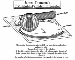
Various simple mechanical analog devices have been invented for performing this integrating step. By the late 19th century analog instruments had been devised for determining areas of randomly shaped portions of survey maps or to integrate functions plotted as graphs (see reference by Abdank-Abakanowicz). Various mathematicians and physicists then began attempting to adapt these to solve differential equations. For example, in the 1860s and 1870s the Scotsman James Thomson (a professor of engineering at Edinburgh University) and his brother William Thomson (a professor of physics at Glasgow, better known today as Lord Kelvin) were engaged in trying to predict the heights of tides. Their attempts to determine an equation that represented tide heights required them to analyze tide records from different ports, and this became so difficult that they proposed using a mechanical disk-sphere-cylinder integrating mechanism as shown in Figure 1. Rotation of the disk corresponds to moving along the x axis of the graph, and the distance of the sphere from the center of the disk corresponds to the height of the graph (the y value). As the disk rotates, an operator must move the sphere in and out corresponding to the y values. If the sphere is close to the center of the disk it will rotate very slowly (a small y value), and if near the edge of the disk (a large y value) it will rotate rapidly. This rotation of the sphere will be transferred (simply by friction) to the cylinder, and the total number of rotations of the cylinder will correspond to the integral of the equation being studied.
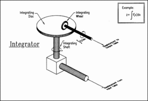
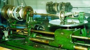
The problem with many of these mechanisms is that they were limited to elementary situations. More complex problems often require the solution of several different differential equations at the same time, and the delicate nature of the friction couplings of the moving components prevented them being joined together into more complex machines. Any attempt to use the output of the cylinder to move another piece of mechanical equipment (say the sphere in a second integrator or some mechanism to add the results of two integrators together) would simply cause the sphere to slip on either the rotating table or the cylinder and thus render useless any potential results. The problem of friction was further exacerbated when, in order to gain more accuracy in the system, the cylinder was replaced by an integrating disk (usually of polished steel or plate glass) and the sphere by an integrating wheel with a knife edge allowing very accurate positioning along the y axis (Figure 2).
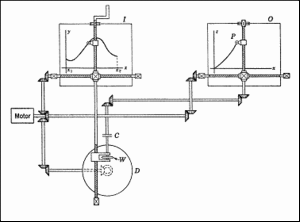
An elementary differential analyzer, capable of integrating only one equation, can theoretically be made by having an input table (labeled I in Figure 3), and integrating device (D) and an output table (O). A motor will drive a curve follower down the x axis of a graph on the input table, while at the same time rotating the integrating disk and driving a pen along the x axis of the output table. The human operator would turn the crank on the curve follower to keep the pointer over the current y value of the graph (thus moving the integrating wheel, W, across the rotating disk), while the output from the integrating shaft, C, moves the output pen up and down recording the results on graph paper.
The major difficulty with this simple device is that it is not suitable for use in complex real-world situations where the mathematical models have several sequential integration steps, i.e., the output of one integration has to be used as the input to the next, and so on. The output from the integrating wheel (W) cannot be mechanically connected to other units because the friction between the knife-edge steel wheel (W) and the steel or glass rotating disk (D) is so small that it does not have the force to drive a second stage of integrating devices.
Lord Kelvin realized that his attempt at creating a mechanical analog device to solve problems involving differential equations would need some type of device to amplify the power (torque) generated by the turning cylinder before it could be coupled to any other system. Unfortunately the technical knowledge of the time did not allow the delicate and highly precise mechanisms to be created.
Achieving Practical Devices
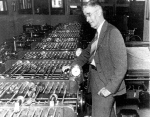
The problem was finally solved in 1930 by Vannevar Bush, a professor at MIT. (He was later to become President of MIT and a very influential advisor to the President of the USA during the Second World War.) Bush began to consider the problem of how to construct a mechanical integrating mechanism when he had to solve some differential equations concerned with an electrical power network. After spending several months attempting to solve just one equation, he decided it was better to spend his time designing an analog computing mechanism that could solve many such equations.
Bush finally resolved the problem of connecting several disk-wheel integrators together for the solution of real word problems when he invented a device that would amplify the torque in the rotating shaft (C), giving enough power to drive other devices while still permitting the delicate movements of the integrating wheel on the disk. This torque amplifier, based on the same principles as a capstan used to raise an anchor on a ship, was an extremely delicate device to construct and maintain. One of the very best differential analyzers had been constructed at the Institute of Physics in Oslo Norway in 1938, just prior to World War Two. Svend Rosseland, an astrophysicist in charge of the machine, realized that the German military would be interested in using this device. After Norway was invaded by Germany, Svend removed the delicate torque amplifiers and, after carefully wrapping them to prevent corrosion, buried them in the garden. This simple expedient rendered this fine machine useless until they were dug up and reinstalled after the war was over.
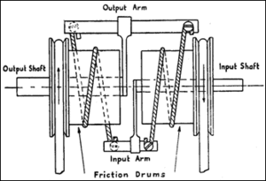
The torque amplifier consisted of two “friction drums” that were rotated by belts attached to electrical motors. An input shaft was connected to the knife-edge wheel of an integrator, and that, in turn, would gently nudge an input arm. The slight movement of the input arm would cause the string to momentarily tighten on the right hand friction drum, giving a pull on the output arm which would then cause the output shaft to rotate with considerable force, the power coming from the left hand friction drum.
It was now possible to have several integrating units with their power amplified outputs being mechanically connected together via gears and the final result connected to a plotting table. The usual format was to have several input tables (one for each function being integrated) on one side of the machine. As human operators followed the graphs with pointers (usually with the aid of magnifying glasses), the output from these tables would be used to position the knife-edge wheel along the radius of the integrating disk. The rotations of the knife-edge disk would be enhanced by the torque amplifiers and fed into an interconnection table of gears and other mechanisms. These mechanisms could add, subtract, and even multiply together two quantities, and then these would, in turn, be combined with others until the final result was obtained. The result was usually sent to a plotting table to produce a graphical representation on paper.
The gearing for the arithmetic operations was well understood. For example, the gears required to add together two sets of values (rotations) is nothing other than the differential gear mechanism used in rear axle of rear-wheel-drive automobiles. Similar gearing systems were well understood for other types of arithmetic operations. The only real problem was that gears have backlash. That is, when a gear is rotated it tends to rotate slightly in the opposite direction when stopped. This lead to inaccuracies in the final result that became more significant as the number of interconnecting gears increased for complex problems. This problem was solved by using gears with specially shaped teeth.
Differential Analyzers in Use
Differential analyzers were one of the main calculating tools in use for solving differential equation problems from the 1930s into the 1950s. Many different machines were produced, usually with increasing numbers of integrator mechanisms and sophisticated interconnection schemes, in universities and research establishments in Europe and America. They were heavily used by the military in doing ballistic calculations to produce the tables that were necessary for artillery aiming. Also, the military used them, or versions of the integrating devices, in such applications as anti-aircraft gun directors and bombsights. In addition they were valuable in solving problems in meteorology, radio antenna propagation, crystallography, electrical networks, and many other fields.
Perhaps the most sophisticated differential analyzer, known as the RDA2 (Rockefeller Differential Analyzer Number 2), was produced by a group led by Vannevar Bush and funded by the Rockefeller Foundation during the Second World War. One of the problems with the entirely mechanical versions was that programming the problem to be solved required the dismantling and recreating of all the gearing mechanisms in the middle of the machine. This process could often take many hours and had to be accomplished with wrenches and other tools. While not a difficult process, it had to be done with care because any slight slack in the system or even slightly misaligned, loose, or slightly worn gears would introduce unacceptable errors in the results.
The RDA2 overcame these problems by replacing the torque amplifiers with sensors that would detect the rotations of the integrating shaft from the knife-edge wheel and pass these values to other parts of the machine via electrical connections. The RDA2 used a special device which could read a paper tape describing the connections to be made, then automatically route the correct signals to the required equipment. This machine was to be used in war-related calculation, and thus Bush was much more concerned with functionality than with cost. Indeed, the cost was so large than no others were ever built. The RDA2 contained 18 integrators and could function at an accuracy of about one part in 1,000 in its calculations—an increase of about a factor of 10 over most differential analyzers at the time.
The existence of this machine, first operational in December 1941, was kept secret during the war. While the machine had been funded and designed prior to America entering World War II, no publicity was given to its completion, and false stories were issued claiming that it had been a failure. It was, in fact, a great success, and it was used in solving countless military problems including such things as tracing back the trajectory of V2 rockets—a calculation that eventually led to the discovery and bombing of their launch site at Peenemünde.
Replacement by Electronic Devices
Prior to the Second World War, the American military had commissioned the construction of differential analyzers similar to Bush’s original machine. These were used in such places as the Army Ballistics Research Laboratory in Maryland and in institutes that were doing work for various military groups. One of the most prominent of these non-military institutes was the Moore School of Electrical Engineering in Philadelphia. They had close connections to the Ballistics Research Laboratory and were also doing work on antenna design and other problems of interest to military groups. When, during the Second World War, it became necessary to recompute a vast number of artillery tables, the differential analyzer at the Moore School was conscripted by the military to help in this work. Despite the fact that all such available resources were being used, the tables project was not making fast enough progress, and the Army sought help from any source it could. This led to a team at the Moore School making a proposal to use vacuum tube electronics to construct a large digital machine capable of integrating the required functions numerically. This machine, named the Electronic Numerical Integrator and Calculator, or ENIAC for short, was to be used on the tables project. While not completed in time to help with its intended purpose, it showed that the analog methods used by devices such as the differential analyzers could, in principle, be replaced by high speed digital machines.
The use of a digital computer to accurately numerically integrate differential equations usually requires it to execute hundreds of thousands of arithmetic instructions. Initially, computers were hugely expensive undertakings and were, for the most part, constructed only in universities and research establishments on an experimental basis. The limited availability and problematic reliability of these machines meant that they were not an effective alternative for solving many of the engineering problems that were arising immediately after World War II. Even when commercially produced electronic computers were obtainable, they seldom had the speed and cost effectiveness that allowed them to compete in solving differential equation problems with the mechanical analog differential analyzers. Several differential analyzers were constructed in the 1950s, usually at major universities, and were kept busy solving military, commercial and research problems. However the development of ever more powerful digital computers meant that, by the early 1960s, most of these problems were being solved on digital computers.
A few attempts were made to create affordable electronic alternatives to the mechanical differential analyzer. The most famous was a machine developed by Northrop Aircraft Inc. in the United States. Known as a MADDIDA (Magnetic Drum Digital Differential Analyzer), it was entirely electronic, and the information for 44 electronic integrators was contained on tracks on a small magnetic drum. First developed in 1949 and demonstrated in 1950, it was designed for smaller research and engineering establishments that could not afford either the expense or the space requirements of a traditional mechanical analog machine. While MADDIDA was an impressive accomplishment, one that received high praise from scientists such as John von Neumann, the Northrop management were more concerned with their other government/military contracts and did little to encourage the MADDIDA creators. Another firm, spun off from Northrop, did produce several different models of the MADDIDA, including ones for airborne military use, but it never achieved any substantial presence in the research marketplace. The developing general purpose digital computer soon was in a position to compete with the MADDIDA, and all work on subsequent improvements stopped.
Acknowledgements
The author thanks members of the STARS Editorial Board and others for review and constructive criticism of this article, with special thanks to Lars Heide for helpful comments and suggestions.
Timeline
- 1886, Mechanical integrators created to help with things such as analysis of ocean tides
- 1931, Bush torque amplifier and first differential analyzer built
- 1934, Differential analyzers began to be built in the US, Britain, Norway, Sweden, and elsewhere
- 1942, Rockefeller Differential Analyzer (RDA2) built
- 1943, ENIAC, an early digital device, used vacuum tube electronics to calculate ballistics tables
- 1949, Analog differential analyzers eventually replaced by digital differential analyzers
- 1959, Differential analyzers finally replaced by general purpose digital computers
Bibliography
References of Historical Significance
Vannevar E. Bush and Harold Locke Hazen. November 1927. Integraph Solutions of Differential Equations. Journal of the Franklin Institute 208, p. 575-615.
Vannevar E. Bush. October 1931. The Differential Analyzer: A New Machine for Solving Differential Equations. Journal of the Franklin Institute 212, p. 447-88. While still a professor at MIT, Bush was responsible for the development of the torque amplifier, the mechanism that made it possible to construct an accurate differential analyzer. His machine was ready for use in 1931, and this paper not only gives construction details but also shows how it might be set up to solve differential equations.
References for Further Reading
Bruno Abdank-Abakanowicz. 1886. Les Intégraphes: La Courbe Intégrale et ses Applications. Étude sur un Nouveau Système d’Intégrateurs Mécaniques. Paris: Gauthier-Villars
John Crank. 1947. The Differential Analyzer. London: Longmans, Green & Co. In this book, Crank describes both the theory and practical details of the differential analyzer with illustrations from the British versions constructed at Manchester and Cambridge Universities. Of particular interest is a photograph showing part of the first experimental differential analyzer model built at Manchester University by Douglas Hartree and Arthur Porter using a Meccano (known in the United States as Erector) construction set.
Owens, Larry W. January 1986. Vannevar Bush and the Differential Analyzer: The Text and Context of an Early Computer. Technology and Culture 27, no. 1, p. 63-95.
Mark Bowles. 1996. U.S. Technological Enthusiasm and British Technological Skepticism in the Age of the Analogue Brain. IEEE Annals of the History of Computing 18, no. 4, p. 5-15.
H. E. Rose. 1948. The Mechanical Differential Analyser: Its Principles, Development and Applications. Proceedings of the Institute of Mechanical Engineers 159, p. 46-54.
About the Author
Michael R. Williams earned a BSc in chemistry from the University of Alberta and a PhD in computer science from the University of Glasgow, Scotland. In 1969 he joined the University of Calgary, first in the Department of Mathematics, and then as a Professor of Computer Science. The history of computing became his main research and teaching interest. He has participated in the publishing of 11 books, 88 articles, and 58 technical reviews. He has worked at several different universities, at the National Museum of American History, and, as Head Curator, at the Computer History Museum in Silicon Valley.
