Milestone-Proposal:First Blind Flight: A Joint IEEE-AIAA Milestone Proposal
Docket #:2013-21
This proposal has been submitted for review.
Is the achievement you are proposing more than 25 years old? Yes
Is the achievement you are proposing within IEEE’s fields of interest? (e.g. “the theory and practice of electrical, electronics, communications and computer engineering, as well as computer science, the allied branches of engineering and the related arts and sciences” – from the IEEE Constitution) Yes
Did the achievement provide a meaningful benefit for humanity? Yes
Was it of at least regional importance? Yes
Has an IEEE Organizational Unit agreed to pay for the milestone plaque(s)? Yes
Has an IEEE Organizational Unit agreed to arrange the dedication ceremony? Yes
Has the IEEE Section in which the milestone is located agreed to take responsibility for the plaque after it is dedicated? Yes
Has the owner of the site agreed to have it designated as an Electrical Engineering Milestone? Yes
Year or range of years in which the achievement occurred:
1929
Title of the proposed milestone:
First Blind Takeoff, Flight and Landing, 1929
Plaque citation summarizing the achievement and its significance:
On 24 September 1929, the first blind takeoff, flight and landing occurred at Mitchel Field, Garden City, NY in a Consolidated NY-2 biplane piloted by Lt. James Doolittle. Equipped with specially designed radio and aeronautical instrumentation, it represented the cooperative efforts of many organizations, mainly the Guggenheim Fund’s Full Flight Laboratory, U.S. Army Air Corps, U.S. Dept. of Commerce, Sperry Gyroscope Company, Kollsman Instrument Company and Radio Frequency Laboratories.
In what IEEE section(s) does it reside?
IEEE/AIAA Long Island Sections
IEEE Organizational Unit(s) which have agreed to sponsor the Milestone:
IEEE Organizational Unit(s) paying for milestone plaque(s):
Unit: IEEE and AIAA Long Island Sections
Senior Officer Name: Senior officer name masked to public
IEEE Organizational Unit(s) arranging the dedication ceremony:
Unit: IEEE and AIAA Long Island Sections
Senior Officer Name: Senior officer name masked to public
IEEE section(s) monitoring the plaque(s):
IEEE Section: IEEE and AIAA Long Island Sections.
IEEE Section Chair name: Section chair name masked to public
Milestone proposer(s):
Proposer name: Proposer's name masked to public
Proposer email: Proposer's email masked to public
Please note: your email address and contact information will be masked on the website for privacy reasons. Only IEEE History Center Staff will be able to view the email address.
Street address(es) and GPS coordinates of the intended milestone plaque site(s):
Cradle of Aviation Museum, 1 Davis Avenue, Garden City, NY 11530; Latitude 370 25.82’ N, Longitude 1220 05.36’ W.
Describe briefly the intended site(s) of the milestone plaque(s). The intended site(s) must have a direct connection with the achievement (e.g. where developed, invented, tested, demonstrated, installed, or operated, etc.). A museum where a device or example of the technology is displayed, or the university where the inventor studied, are not, in themselves, sufficient connection for a milestone plaque.
Please give the address(es) of the plaque site(s) (GPS coordinates if you have them). Also please give the details of the mounting, i.e. on the outside of the building, in the ground floor entrance hall, on a plinth on the grounds, etc. If visitors to the plaque site will need to go through security, or make an appointment, please give the contact information visitors will need.
This will be a joint designation with the AIAA.
The milestone plaque will be installed in the Mitchel Field Flight Safety exhibit of the Cradle of Aviation Museum, 1 Davis Avenue, Garden City, NY 11530. The museum is located on the former site of the Mitchel Field U.S. Army Air Corps Base and the plaque will located just a few hundred feet from where the flight’s takeoff and landing originated.
Are the original buildings extant?
The original wooden airfield buildings that date back to World War I were replaced by brick buildings in the early 1930s several of which have been incorporated into the present museum.
Details of the plaque mounting:
The plaque will be securely mounted in the museum on the wall of the Mitchel Field Flight Safety Exhibit.
How is the site protected/secured, and in what ways is it accessible to the public?
The plaque will be located inside the museum. The museum is protected by security personnel during visitor hours when it is open and by an alarm system when it is closed. The museum is open daily during the summer and from Tuesday to Sunday the rest of the year.
Who is the present owner of the site(s)?
The County of Nassau, NY and is managed by the Cradle of aviation Museum.
A letter in English, or with English translation, from the site owner(s) giving permission to place IEEE milestone plaque on the property:
A letter or email from the appropriate Section Chair supporting the Milestone application:
What is the historical significance of the work (its technological, scientific, or social importance)?
After World War I the role of aviation expanded from primarily the military to commercial enterprises with mail, cargo and passenger flights. Weather and visibility could disrupt regular flights which were required for the new aviation industry to be commercially successful and for the Post Office to establish overnight delivery schedules.
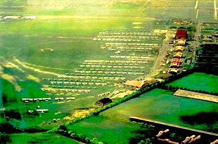
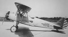
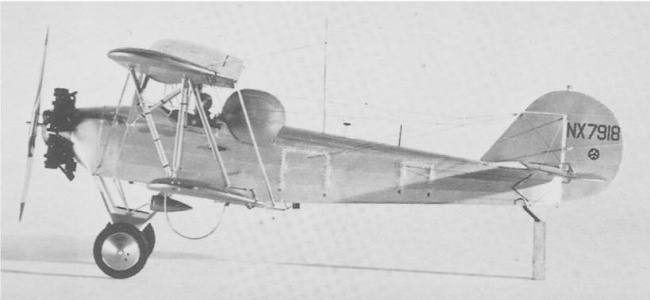
During the 1920s there was slow but steady progress in the development of cockpit instruments to assist pilots flying during conditions of low visibility. At the beginning of the decade, the instruments which were primarily mechanical, could provide altitude, attitude, direction and air speed information, but not an aircraft’s spatial position, which was crucial during landing. Instruments and navigation aids were needed which would allow an aircraft to be flown on a course in fog, in any condition of visibility or no visibility. The first blind flight occurred on September 24, 1929 when U.S. Army Air Corps pilot, Lt. James Doolittle*, at the Guggenheim’s Full Flight Laboratory at Mitchel Field (Figure 1), took off in a specially instrumented Army Air Corp NY-2 Husky aircraft (Figure 2a) built by the Consolidated Aircraft Corporation with Lt. Benjamin Kelsey** as his safety officer and landed after a fifteen minute, 20 mile, flight without ever seeing the ground. At the time the NY-2 Husky was the world’s most instrumented aircraft engaged in blind flying research. The rear cockpit contained the blind flying displays and during the trials preceding the blind flight was covered by a special hood to eliminate external references (Figure 2b.)***
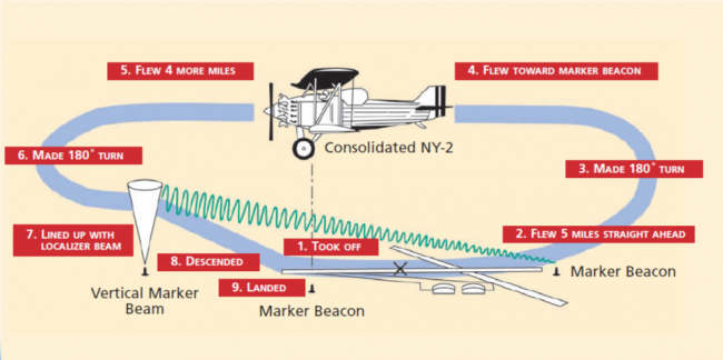
In Doolittle’s own words, “We both got into the plane, and the hood over my cockpit was tightly closed. I taxied out and took off toward the west in a gradual climb. At about 1,000 feet, I leveled off and made a 180-degree turn to the left, flew several miles, then made another left turn. The airplane was now properly lined up on the west leg of the Mitchel range, so I started a gradual descent, I leveled off at 200 feet and flew level until I passed the fan marker on the east end of the field. From this point I flew the plane down to the ground using the instrument landing procedure we had developed. The whole flight lasted only 15 minutes. So far as I know, this was the first time an airplane had taken off, flown over a set course, and landed by instruments alone.”
Crucial to the success of the flight, in addition to the newly developed Kollsman Altimeter and the Sperry Directional Gyro and Artificial Horizon, was the radio range and marker beacon developed by the Bureau of Standards and the special radio receiver with a vibrating reed display built by the Radio Frequency Laboratories. The special instrumentation installed on the NY-2 also included a radio transmitter and receiver with a trailing wire antenna that provided voice communications. At the time the standard installation utilized only Morse code transmitters and receivers which made their use problematic under difficult flying conditions. A unique application of the radio on the NY-2 was its use to synchronize the Kollsman Altimeter with the ground barometer reading.
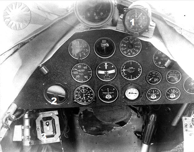
The cockpit (Figure 3) was outfitted with a number of the standard cockpit instrument displays of the time as well as the special ones developed by the Sperry Gyroscope Company, the Kollsman Instrument Company and the Radio Frequency Laboratories. Among them were the: Kollsman Altimeter (#1, upper right in Figure 3), Standard Altimeter, Magnetic Compass, Air Speed Indicator, Sperry Artificial Horizon (#2, first row left in Figure3), Turn & Bank Indicator, Rate of Climb Meter, Tachometer, Chronometer, Earth Inductor Compass, Oil Pressure, Oil Temperature, Ammeter, Voltmeter and the Vibrating Reed Localizer Display (#3, lower left in Figure 3). The NY Times which reported the flight in detail stated that only three specially designed instruments had been installed and included a photo of the cockpit instrument panel identifying each of the instruments.
The Sperry Directional Gyro was not among those identified. In the 1930 Vol. 6, No. 2 issue of, “The Sperryscope,” an article about the newly developed gyroscope-based instruments for aircraft states that both the Artificial Horizon and the Directional Gyro were installed in Doolittle’s plane. Richard Hallion in his book, Legacy of Flight, also states that a Gyrocompass (Directional Gyro) was installed in the plane, but the cockpit instrument panel shown in his book has a somewhat different layout from that in the NY Times photograph. During the test flights preceding the blind flight, different instrument configurations had been tried. No doubt the Directional Gyro had been included among them, but on the basis of the NY Times photograph and story, it appears not to have been installed during the blind flight. A photo in the Guggenheim report, Equipment Used in Experiments to Solve the Problem of Fog Flying, shows the Blind Flight Laboratory’s final cockpit instrument panel with the Sperry Directional Gyro but does not include the vibrating reed display.
- When James Doolittle was selected to head the Full Flight Laboratory, he was officially “borrowed” from the Air Corps for a one year period of detached service and had received in 1926 his doctorate in aeronautical engineering from M.I.T. During World War II he volunteered for and received General H.H. Arnold's approval to lead the top-secret attack of 16 B-25 medium bombers from the aircraft carrier USS Hornet on April 18th in 1942, with targets in Tokyo, Kobe, Yokohama, Osaka, and Nagoya. The success of the raid was a big morale booster for the United States in the aftermath of successive victories by the Axis during the immediate months after the beginning of the war.
- Benjamin Kelsey graduated M.I.T. with a BS in June 1928, and stayed to teach and conduct research work in the aeronautics department. He flew for commercial concerns as well as privately obtaining a transport pilot’s license. He joined the United States Army Air Corps and was commissioned a second lieutenant on May 2, 1929. He was assigned to the Full Flight Laboratory at Doolittle’s request and at Harry Guggenheim’s insistence flew as Doolittle’s safety pilot during the NY-2 Husky instrument flights. During the first 'blind' instrument flight on September 24, 1929, he showed observers that he was not in control by keeping his hands visible outside the cockpit.
- For a film clip from the Getty Archives showing Lt. Kelsey and Lt. Doolittle in the NY-2 Husky with Lt. Doolittle pulling the hood over the front cockpit and describing the contributions of the Sperry Artificial Horizon and Directional Gyro, click on http://www.gettyimages.com/detail/video/james-jimmy-doolittle-performs-first-blind-flight-news-footage/145012946. Note that on the model of the plane shown in the preceding photograph the hood is shown on the rear cockpit.
- Benjamin Kelsey graduated M.I.T. with a BS in June 1928, and stayed to teach and conduct research work in the aeronautics department. He flew for commercial concerns as well as privately obtaining a transport pilot’s license. He joined the United States Army Air Corps and was commissioned a second lieutenant on May 2, 1929. He was assigned to the Full Flight Laboratory at Doolittle’s request and at Harry Guggenheim’s insistence flew as Doolittle’s safety pilot during the NY-2 Husky instrument flights. During the first 'blind' instrument flight on September 24, 1929, he showed observers that he was not in control by keeping his hands visible outside the cockpit.
What obstacles (technical, political, geographic) needed to be overcome?
Examining the roles of the key organizations that made the first blind flight and landing possible best demonstrate the technical, political and geographic obstacles.
The Daniel Guggenheim Fund for the Promotion of Aeronautics.
The fund was established in January, 1926, with funding from Daniel Guggenheim in the amount of $2.5 Million with Harry Guggenheim*, Daniel’s son, a WW I aviator himself, as its President. Its purpose was to promote aeronautical education, assist in the education of the aeronautical sciences and to further the development of commercial flying for carrying both passengers and cargo. Having accomplished its purposes, the fund was liquidated in February, 1930. Among the projects created by the fund was the establishment of the Full Flight Laboratory for the Study of Fog-flying which was located at Mitchel Field on Long Island, NY, about a two hour’s drive from Harry Guggenheim’s home in Sands Point on Long Island Sound.
At the time the generally accepted practice of commercial pilots was to turn back or to cancel a flight in the presence of fog, which made air travel less reliable than other means of transportation. A committee consisting of representatives of the War and Navy Departments, Department of Commerce and the Post Office Department established the goals of the Full Flight Laboratory. They were: 1) The dissipation of fog; 2) The development of means to locate flying fields from the air regardless of fog; 3) The development of instruments to accurately display the altitude of an airplane above the ground and replace the use of barometric instruments which showed the altitude above mean sea level; 4) The Improvement of instruments allowing airplanes to fly in fog; and, 5) The penetration of fog by light rays. Of the five goals, the laboratory’s resounding success was in achieving the fourth goal, demonstrating the use of improved instruments allowing airplanes to fly in fog.
- Daniel Guggenheim served in the United Sates Naval Reserve overseas during World War I as a pilot and left the service as a Lt. Cmdr. In 1924, as President of the Daniel and Florence Guggenheim Foundation which was the governing body for the Full Flight Laboratory, he sponsored Robert H. Goddard's private research into liquid fuel rocketry and space flight and founded the first of several schools of aviation at New York University. Charles Lindbergh wrote his book, “We,” while a guest at Harry Guggenheim’s home, Falaise, in Sands Point, NY. Falaise, which is located on the Guggenheim estate in Sands Point, is open to visitors. He and his wife, Alicia Patterson, were founders of the newspaper, Newsday.
The Sperry Gyroscope Company Instruments: The Horizontal Situation Display and the Gyrocompass.
The company, located in Brooklyn, was founded in 1910 by Elmer Ambrose Sperry to manufacture chiefly his own inventions, initially the marine gyrostabilizer and the gyrocompass. During World War I the company diversified into aircraft components and instruments including radio direction finders, searchlights, bombsights, fire control systems and navigation equipment.
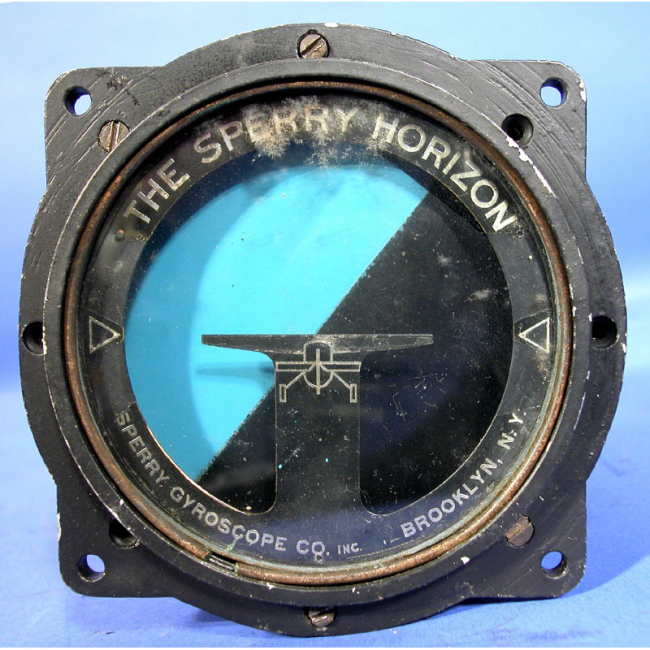
Two gyroscope based instruments were developed for the Full Flight Laboratory to be installed in the NY-2 Husky as part of the cockpit instruments. An artificial horizon display to show an aircraft’s attitude relative to the ground and a directional gyro which would not be affected, as would be a magnetic compass, due to magnetic field anomalies, suspension friction and the alignment lag of the indicator pointer during turns. Doolittle had proposed to Elmer Sperry, Sr., the design of an integrated instrument whose display depicted that of a directional gyro superimposed on an artificial horizon.
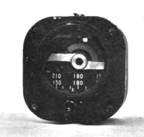
Elmer Sperry indicated that such an instrument could be built, but instead advised the design and construction of two separate gyroscope based instruments, an artificial horizon display and a directional gyro to be designed and built under the guidance of his son, Elmer, Jr. The Artificial Horizon Display (Figure 4a) was to show a pilot whether the aircraft was flying straight and level, diving or banking and the Directional Gyro (Figure 4b) to display the aircraft’s heading relative to North. Both instruments depend upon the inertial property of gyroscopes, which maintains them fixed with respect to space, when they have attained their designed rotation speed.
Once up to speed, the Directional Gyro is aligned to the heading of the magnetic compass or other directional reference. Both devices at the time were air driven whereby air from a pitot venturi was directed against buckets on the rotors of the gyroscopes so that they would spin at their designed rotation speeds of 10,000 RPM. Today, both electrical and air driven versions of the devices are made, air driven for smaller planes flying at lower altitudes and electrically driven for planes at higher altitudes.
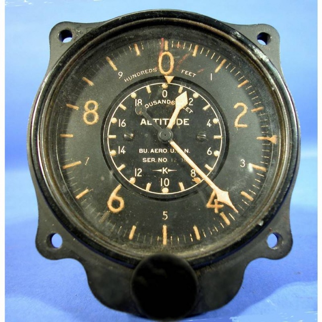
Kollsman, a perfectionist, contacted Swiss watchmakers who made precision gears to drive the altimeter’s needles. He also developed an improved diaphragm with a reduced lag in response to changes in pressure. What made the instrument so valuable to Doolittle, besides its improved accuracy, was that it had two hands and a multiplication factor of twenty between them. The fast moving hand made a complete revolution for each thousand foot change in altitude which meant a change of 5/32 of an inch for each twenty feet of altitude, an order of magnitude increase in accuracy over what was then available. The altimeter’s local barometric pressure setting could be synchronized with the local barometric pressure during flights using the then advanced voice radio transmitter and receiver which had been installed on the NY-2 Husky aircraft. A window for setting the local barometer pressure was introduced in a later model. It became known as the Kollsman Window.
The National Bureau of Standards Radio Division.
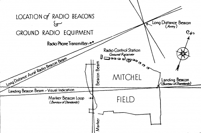
The National Bureau of Standards Radio Section was, at the time, part of the Department of Commerce. The Radio Section designed a two-leg radio range and fan-type marker beacon whose signals could be received by the plane’s radio receiver. The homing range was installed on the west side of Mitchel Field and the marker beacon was installed along the leg of the homing range transmitter on the east side of the field. The Bureau’s work in the development of radio guidance systems began in the early 1920s when a pilot flew along a course designated by signals from two ground transmitters and a prototype radio beacon was produced in 1923 for the Army Air Service. It was not until 1928 that Harry Diamond, an engineer in the Radio Section, proposed the use of a modified low-frequency (330 KHz) ranging system (the Localizer) that would provide a pilot with the aircraft’s lateral position with respect to the runway by transmitting a series of A’s and N’s which would meld into a continuous audible tone when the aircraft was on the glide slope for landing. The addition of two high-frequency (97.3 MHz) beacons in line with the approach path would provide two position fixes. The first fix was the outer marker and the second, the inner marker, which indicated the airplane was within the airport’s boundaries and could land safely.
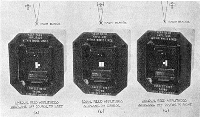
For the blind flight, a low frequency localizer was borrowed from the Bureau. The localizer was a visual type employing a pair of metal reeds, mechanically tuned, and driven by a receiver specially designed by the Radio Frequency Laboratories. When the aircraft was on course, the two reeds appeared to be the same length and when the plane was to the right or left of the course, it would be represented by the reed on that side and the pilot would turn the plane toward that reed (Figure 6).
Figure 7 shows the location and effective coverage of the range and localizer beacons. The location of the Radio Control Station is just outside what is now the main entrance to the Cradle of Aviation Museum. Figure 7 depicts the course flown by Doolittle and Figure 8, the route flown. Doolittle in his autobiography states that the entire flight lasted about 15 minutes without estimating the distance flown. The NY Times in a story covering the flight gave the distance as 15 miles.
The Radio Frequency Laboratories.
The Radio Frequency Laboratories (RFL) was founded in 1922 and was located in Boonton, NJ. The company owned a number of radio receiver patents for volume controls and amplifier circuits and was exploiting the use of Bakelite in radio equipment. By 1929, the company was already well known for the development and manufacture of airborne radio receivers including special components including vacuum tubes for their receivers. During WW II, the company became famous for the ARC series of aircraft transmitters and receivers known generically as, “Command Sets.”
RFL was asked by Doolittle to build a receiver to pick up the radio range (Beacon) signals and drive a vibrating reed display as shown in Figure 6 but also to be able to receive voice transmissions from the ground station which transmitted weather and the barometer pressure for synchronizing the on board Kollsman Altimeter. Figure 9 shows the specially designed and constructed Beacon receiver that covered the frequency range of 285-370 KHz. It was a five tube receiver consisting of two tuned RF stage, a triode tube grid leak detector followed by two stages of audio amplification. Note the small control box to the right in Figure 9 which was used to select the vibrating reed display or headphones for voice reception or audio tones for the “A” and “N” Morse Code localizer signals.
RFL also designed and constructed a one tube code transmitter operating at a frequency about 7.4MHz. with a fixed length, rather than a trailing wire, antenna. Control of the set and the transmitting key was located on the right side of the rear cockpit. RFL was only 35 miles from Mitchel Field and Doolittle flew there on several occasions in the NY-2 Husky to have the radio equipment installed. ( A second voice transmitter was built by Western Electric and installed by the Bell Telephone Laboratory.)
What features set this work apart from similar achievements?
The achievement of the first blind flight and landing was the result of an unusual cooperative effort primarily involving the Daniel Guggenheim Fund for the Promotion of Aeronautics, the U.S. Army Air Corps, the Department of Commerce, the Sperry Gyroscope Company, the Kollsman Instrument Company and the Radio Frequency Laboratories. Other companies, the Pioneer Instrument Company, the Taylor Instrument Company and the Bell telephone Laboratories contributed as well.
Doolittle’s successful blind flight and landing demonstrated that having and being able to use accurate and reliable instruments was the key to safe flying, under near zero visibility conditions and that contrary to the belief of many pilots at the time that being able to fly, “by the seat of my pants,” was the more important skill.
Of all the organizations that contributed to the success of Doolittle’s flight, were it not for the Full Flight Laboratory established by the Daniel Guggenheim Fund for the Promotion of Aeronautics, Doolittle’s achievement that helped pave the subsequent rapid growth of the aviation industry might well not have occurred until several years in the future. Furthermore, it paved the way to the all weather microwave landing systems that are currently used.
References to establish the dates, location, and importance of the achievement: Minimum of five (5), but as many as needed to support the milestone, such as patents, contemporary newspaper articles, journal articles, or citations to pages in scholarly books. At least one of the references must be from a scholarly book or journal article.
NOTE: Extensive use was made of the Cradle of Aviation Museum’s library of original material and its collection of aviation related photographs.
- J. H. Dellinger, H. Diamond and F. W. Dunmore, Development of the Visual-Type Airway Radio-Beacon, Proc. of the I.R.E., Vol. 18, May 1930.
- H. Diamond and F. W. Dunmore, Development of the Visual-Type Airway Radiobeacon System, Proc. Of the I.R.E., Vol. 19, April 1931.
- H. Diamond and F. G. Kear, A 12-Course Radio Range for Guiding Aircraft with Tuned Reed Visual Indication, Bu. of Stds. Journal of Research, Vol. 4, September 18, 1929.
- R. P. Hallion, Rhythms of Speed and Streamlining, the Transformation of American Aviation, 1935: The Reality and the Promise Conference, April 7-9, 2011, Hofstra Univ., Hempstead, NY.
- Blind Plane Flies 15 Miles and Lands; Fog Peril Overcome, The New York Times, p.1., September 25, 1929.
- G. E. White, Tubes, Transistors and Takeovers, Avionics, Yesterday, Today and Tomorrow, June, 1984.
- E. M. Conway, Blind Landings, The John Hopkins University Press, Baltimore, MD., 2006
- General J. H. Doolittle with Carroll V. Glines, I Could Never be so Lucky Again, Bantam Books, NY, 1991.
- Daniel Guggenheim Fund, The Final Report of the Daniel Guggenheim Fund for the Promotion of Aeronautics 1929, September 1930.
- McCormick, B.W., Newberry, C.F., Jumper, E., Aerospace Engineering Education During the First Century of Flight, A.I.A.A., June 30, 2004.
- White, G.E., Tubes, Transistors and Takeovers, AOPA Pilot, June, 1984.
- Irwin Unger and Debi Unger, The Guggenheims, HarperCollins Publishers, NY, 2005.
- Leary, William, The Search for an Instrument Landing System, 1918, Innovation and the Development of Flight, edited by Launis, Roger, Texas A&M University Press, 1999.
- New Radio Beacon can Sift Course from Among 12:Device Perfected by Bureau of Standards, New York Times, Aug. 18, 1929.
- Whitaker, O. B., “New Gyroscopic Instrument Contributes to Safe Flying,” The Sperryscope, Vol. 6, No.2, Sperry Gyroscope Company, 1930.
- Hallion, Richard, Legacy of Flight, University of Washington Press, Seattle, 1977.
- Helfrick, Albert, Electronics in the Evolution of Flight, Texas A&M University Press, 2004.
- Equipment Used in Experiments to Solve the Problem of Fog Flying, The Daniel Guggenheim Fund for the Promotion of Aeronautics, Inc., New York City, March 1930.
Supporting materials (supported formats: GIF, JPEG, PNG, PDF, DOC): All supporting materials must be in English, or if not in English, accompanied by an English translation. You must supply the texts or excerpts themselves, not just the references. For documents that are copyright-encumbered, or which you do not have rights to post, email the documents themselves to ieee-history@ieee.org. Please see the Milestone Program Guidelines for more information.
NOTE: The photographs used in the proposal have either been obtained from the Cradle of Aviation Museum's photo archives with permission or other public sources without indicated permission requirements.
