First-Hand:The Life of an Engineer
Submitted by Arthur Cable, CEng., FIET, MIMechE, LSM, AIEE
Associations
I became an associate member of the American Institute of Electrical Engineers in 1951 and a senior member in 1957 when I was working in Canada. I was one of the founder members of the UK and RI section of the Institute of Electrical and Electronics Engineers (IEEE) in 1963. I was a member and subsequently became a fellow of the IEE in 1972 (now IET) and have been made a life member of the IEEE. I became a Chartered Engineer in 1966 and a member of the Institute of Mechanical Engineers in 1976.
Childhood memories
I was fourteen years of age the year that war broke out, brought up since the age of four by my maternal grandmother, Daisy Cable, and her second husband, Thomas Banks Blaylock, generally known as Tom, in the mining area bounded by Moresby, Whitehaven and Lowca in the north west of England.
My earliest recollections revolve around the family home of Tom’s father, a large house with a very large garden built on a hillside and known locally as The Big House. From the rear it had wonderful views over undulating countryside falling away in the distance to the Solway Firth with ships passing and from where, on a fine day, one could see as far as the Isle of Man. From the front and side the panorama of the Cumbria Fells and Mountains was clearly visible. These views were far removed from the spoil dumps, mine buildings and ancillary works normally associated with the dying coal mining industry of that period in other local mining areas and mining villages within the area known then as West Cumberland.
As I grew older grandfather taught me the day to day operations of the lighting system in the house which was changed from oil lamps and candles to a semi automatic low pressure gas system produced on a water drip tray on which was a layer of Carbide (Carbide, especially Calcium CaC2 yields Acetylene gas when moistened). As I recall this system was prone to making popping sounds from time to time and was quickly replaced after the end of the war when the electric supply became available in the countryside. Grandfather also taught me how to operate and repair the semi automatic drip feed system for maintaining the Coke fed and ash disposal system for the water heater boiler, which maintained the required temperature in the green houses during the winter months.
In the summer we would sometimes go on picnics to Loweswater or even to Crummock Water and once we went to see Mr John Foster Clarke at his large house Hassness on the lakeshore of Buttermere. Mr Foster Clarke had his own small, 50 kVA hydroelectric generating plant, stand by diesel generator and a large lead acid battery bank in his own power station and he showed me around the equipment and explained how it worked.
My introduction to the world of work
As I grew older it was my great grandfather and his two sons (Tom and Ernie) who introduced me to the reality of working life in a mining community. This included an introduction to the various aspects of coal mining including the treatment of coal, the varied by-products of coal and the many uses to which it was put. Today many of these have been superseded by the by-products of oil and other synthetics. Moresby Pit although only some four miles away lay in a fold of the hills and out of sight and sound of the Big House and its gardens and hot houses.
Great Grandfather was a salaried company employee in charge of and responsible for what was generally known as the Lamp Cabin, a much more responsible position than my mundane description will imply. The term Lamp Cabin within a colliery complex at that time did not refer to a cabin in the accepted sense. Normally it was a separate building, containing a small office, two store rooms, one for the Carboys of Sulphuric Acid and Distilled Water and the other for the storage of the various parts required for the maintenance of the electric lamps and the oil lamps required in testing for methane gas. It also included the bench areas for the day-to-day cleaning and maintenance of the miners’ lamps, together with the charging and storage racks for holding them and the lamp issue and recovery stations. This was where the miners, and all personnel proceeding underground, deposited their identity tokens, collected and returned their lamps and had their tokens returned to them on their return to the surface at the end of their work period.
Upon presentation of his token the miner, manager, the daily shaft inspection officers and others descending into the mine would be given a fully charged electric lamp and if authorised a Davey Safety Lamp; a type of oil lamp suitably constructed for testing for the presence of gas in the mine. They would have their token taken from them and placed on the hook over a similarly numbered cell. Upon their return from underground they presented their lamp and stated their token number, which was then given back to them. The electric lamps and the oil lamps used for testing for the presence of gas were checked and serviced daily. Upon return to the lamp cabin the metal encased lead acid section of the unit was unscrewed from the lamp assembly, (towards the end of the late thirties this also included the nickel iron battery units), then visually checked and placed into the appropriately numbered battery racks for charging in preparation for the following day.
It was also about this period that Ringrose Company introduced a rather complex, heavy, square shaped electric lamp and combined gas detector unit. I understand that this particular battery powered lamp/gas detection system never became popular with the miners due primarily to the weight which was in the region of five and a half pounds and over twice the weight of the nickel iron units, although these were considerably heavier than the compact battery and detachable composite helmet lamp in use today. This reluctance is understandable when one remembers that, before the general introduction of the Bathgate Hat which permitted the lamp unit to be clipped to the miners’ head gear, with the battery unit encased in a lightweight acid proof composite case hanging from the waist, the normal and most comfortable position for the miner to carry his electric lamp was hanging from his belt between his legs, leaving both hands free for carrying the various tools required for working at the coal face.
During these visits I gained a working knowledge and understanding of the different areas of a working mine, knowledge that stood me in good stead when I later applied for my apprenticeship. These areas included the smithy, the wood and prop yard with its range of various sized pit props, including ‘Norways' and hardwood wedges, the boiler house with its six Cochran tube boilers, the engine room with its winding drums and the pithead. It was on these and many other similar occasions during my school holidays or Saturday visits that I was encouraged to ask questions - these were always answered with understanding and helpful descriptions and explanations. The Saturday afternoon visits were always, to me, rather special. It was during these visits that I learnt about the many engineering disciplines and the importance of their interaction to ensure the safe and efficient working of a coal mine. I also learnt about the ancillary services that were required to keep it operating safely. The friendly and helpful attitudes of the various trades, engineers, artisans and people who made up the work force of the mining industry provided me with the basis for a life long interest in and enthusiasm for engineering.
My apprenticeship
In 1941 I commenced a registered apprenticeship which required not only being taught the practical work required by a Mining Engineer in those days, but also a recognised academic course of study to be undertaken to obtain an acceptable engineering qualification. This could take up to five years to complete, but since then I have discovered that my learning period has lasted a lifetime. In late September 1942 the National Industrial Council for the Electrical Contracting Industry provided me with a Certificate of Registration in respect of Juvenile Labour. This was apparently a War Time Regulation, which permitted me to receive, as a juvenile, the necessary practical working knowledge and training during my apprenticeship.
The periods of work experience, organised by my college during the college recess periods with the various heavy engineering companies in the vicinity were an important part of my learning and took up most of my spare time. This period of my life was very interesting although it extended for almost five years during which if I was not working, I was studying, and if I was not studying I was working or travelling for work or study. My early engineering experiences were not restricted only to contact with electricians and work sites, the following is a reflection on the effects and decisions of management which provided me with an important learning experience which I was later to call on in my work in Singapore.
The construction of the Skelton Grange Radio Transmission Station in the eastern central area of Cumberland during the war years was a matter of some priority after the majority of Europe had succumbed to the onslaught of the German war machine. To counter, interrupt and jam the German radio propaganda broadcasts and enable our own view of the war to be received in the occupied countries it was necessary to have direct control of a powerful radio transmission complex. It was for this purpose that the twin radio transmission sites of Skelton Grange were constructed.
Radio Transmission Stations are complex, the layout of the arial arrays requiring large areas of land, and in this instances multiple series of security fencing, but comparatively small building areas to house the valve rooms, cooling plant, air conditioning plant, control rooms, offices etc. and in the case of Skelton Grange its own 100% standby generating capacity. The overall project was under government control and direction, the main contractor was an amalgamation of Marconi Valve/English Electric group as site construction managers and as the suppliers of the major equipment. They, in turn, had engaged local sub contractors for the electrical installation, plumbing, heating, ventilating and similar non-specialist works.
The village of Skelton then consisted of a few houses, a church, a public house, a telephone kiosk, and little else. Well off the beaten track and with a twice-daily bus service, morning and afternoon timed to suit the transport of children from the surrounding countryside to and from school at Penrith. It was not ideal for the transport of workmen, especially to a work site that was rated top priority with respect to completion. A dispute had arisen between the sub contractor’s workmen and their management regarding the subject of travelling time to and from the work site. The site agent had scheduled a meeting of all interested parties for nine thirty one morning. It was within a few minutes of ten o’ clock when the last person, who turned out to be the director of the major electrical sub contractor, arrived giving as his excuse that Skelton was difficult to find and quite a long distance from Carlisle. The meeting started and the discussions carried on throughout the morning on the problem, seen as the non productive travelling time involved in getting to and from the site and who was going to pay for it. The bus service took one and a quarter hours to get from Carlisle to Skelton Grange number one site, and it was then almost a twenty minute walk to the number two site.
The general agreement of all parties, except one, was that a formula based upon the existing General Agreement between Electrical Trades Union and Employers which stated that non productive working time, which already included unreasonable travelling time, would be applied on a one way basis. At four o clock however, the director who had arrived late was still maintaining that his company would not accept the ruling and indicated that there was a further local clause to the General Agreement, which stated that any site within a twenty-mile radius of Carlisle was not subject to the unproductive working time rule. He then stated that as the crow flys Skelton was within a twenty-mile radius of Carlisle and therefore his company was within their rights not to agree payment for travelling time to or from work.
The site agent, who was a long time employee of the main contractor, looked round the table, then with a completely straight face said very slowly and deliberately, ‘Sir you have an approved and accepted contract with my company, authorised by the Ministry, in which you and we undertook to complete this work by a stated time. You are not meeting your target dates. Your employees will be on this site at eight thirty tomorrow morning and will leave at five o clock according to the contract between our two companies. How you arrange transport for your employees, by means of your flying crows or otherwise, are your problem not mine. My company will be informed of your attitude immediately this meeting comes to a close, and unless there is any other business, it is now closed’. At that time I was a not so young apprentice who was on daily loan to the site agent and had been given the task of taking the minutes of the meeting. The above quote is a more or less accurate recollection of my hand written scribble.
It was some time later that I learnt the outcome, although the immediate results were evident on the morning after the meeting when the contractor’s site staff arrived on both sites by eight thirty in their own transport and did not leave until after five o clock by the same method. Apparently the site agent had kept his word. He had called his superior in Stafford, who in turn had contacted the appropriate person in the Ministry, who that evening had contacted the visiting director’s managing director who was also the principle shareholder of the sub contracting company. From the speed of the results I have always assumed that someone clearly indicated to the errant director, not only the error of his management technique but also that there was a war on!
Working away from home in war-time Britain
It was quite common for contractor’s staff from the north of England to be seconded to other areas of the country to work on contracts when and wherever it was decreed that urgent and necessary war work was running behind time, even if it required the men to travel to places like Bath or Bristol from their home bases in the north like Carlisle and Newcastle. As would be expected during wartime the range and variety of work that a small jobbing electrical contracting firm was expected to cover in some instances greatly exceeded the technical capabilities and experience of its qualified electricians. However, the opportunities to learn from the older and more widely travelled and experienced engineers of the major electrical manufacturing companies of English Electric, Metro Vickers, British Thomson Houston, British Callender Cables were extensive if you were willing to work, travel and accept responsibility.
Towards the end of the war in Europe I had volunteered on three occasions to join the forces, however, after each medical, I was declared not only ‘reserved’ but also medically unfit. Officially my apprenticeship was completed during 1946 by which time I had completed all the required practical work including office and design work and work on construction sites for the companies mentioned above. This involved the installation, testing and putting to work of a 30 MW turbo generator, 150 miles of 132 kV twin circuit steel tower overhead line, two 33 kV wood pole single circuit overhead lines and two 66 kV distribution sub stations.
During the final year of my apprenticeship I remember attending, a conference sponsored by the United Nations Educational, Scientific and Cultural Organisation detailing the devastation existing throughout Europe. Two of the speakers discussed the aims of UNESCO and detailed the various forms of assistance required and the extent to which they could and would provide assistance to any genuine volunteer. The long and short of this was that I ended up as a volunteer in Northern Italy helping with the reconstruction of a war damaged institutional home for children from all over Europe.
Singapore
How did I end up in Singapore? I had applied for and been accepted as a junior electrical engineer with a well known and respected company based in Singapore and trading under the name of United Engineers. I later learned that I was in fact replacing a highly experienced electrical contracting engineer. In those days (1947) the fastest passenger liners did the journey in three weeks, the flying boats took ten and a half days. This was the mode of travel that I took to Singapore and an experience I will never forget. My work in Singapore was varied, interesting and challenging. The following are a few examples.
A critical learning experience
Whenever I have reason to look back on this particular contract I realise that it provided one of the most lasting, instructive, practical learning experiences of my career and one from which the knowledge gained was to prove, many times, to be of great assistance during my future career.
The company I worked for held the agency for The Marconi Valve Company, which had received (before the war) an order for the upgrading of the Jurong Wireless Transmission and Receiving Station, which was situated in a then rather remote part of Singapore Island. The project office, based in Chelmsford, England, had indicated to the UK client in their contract documents that installation and pre commissioning testing would be carried out by their local agent prior to the arrival of their skilled engineering engineers from Chelmsford who would carry out the putting to work and commissioning of the valves and associated control systems as and when required.
The first intimation that I received of the above was one afternoon when I returned to the office to be asked what I knew about the Marconi Valve Company by the Chief Mechanical Engineer. Foolishly I told him of the Skelton Grange period and my three-month training at Marconi factory. He then gave me a copy of a folder listing all the technical specifications, plans, diagrams and other relevant paper work to review and instructed me to let him know if there was any reason for the mechanical and civil sections of the company to be involved. My halfhearted excuses were overruled by his asking if this equipment was electrical, mechanical or civil. My reply that there may be some air conditioning equipment involved, led to the response that in that case I should tell our air conditioning engineer, and let him worry about it.
As I was leaving his office his secretary indicated a medium sized tea chest standing alongside her desk and said it contained the rest of the documentation from Marconi, which I needed to read. It took me the rest of the afternoon to absorb the contents of the folder and the tea chest and to realise that the shipment of equipment had already arrived and that I had to try to find out where it was! My remit and responsibility eventually covered tracing, checking for completeness, reinsurance for transport to site, clearing from the bonded warehouse, transportation of the entire shipment to site, site preparation, all installation and testing at site and full operational assistance, with the existing station staff, in bringing the extended London, Singapore, (Jurong Broadcasting Station) Australia Radio Link into operation. What did I learn? That there are many disciplines, other than engineering, of which more than a working knowledge is required when dealing with multi national engineering contracts.
Generator Problems
Not all of my work in Singapore was involved in electrical engineering contracting; from time to time it covered other tasks and industries as this account of some of the work performed at the Malayan Guttas Factory shows. The generating capacity at the Malayan Guttas factory, which refined chicle used in the production of chewing gum, consisted of 2 x 600 kVA with 0.8 pf Westinghouse generators driven by Chicago Pneumatic Diesel Engines. A third unit was installed and had been mechanically checked and I was responsible for the testing, commissioning and putting to work. At that time there was insufficient loading to keep two generators running one hundred percent of the time and the manager of the plant had reverted to single generator operation when the factory loading permitted.
The two existing units had been giving constant trouble since their first start up when the drying out time had been out of proportion to the normal expectations for such units. However, insulation measurement readings at each start up had become lower and lower and the delay, caused by the necessity to partially dry out the windings before applying an electrical operational load, was taking longer and longer before start up and subsequent loading could safely be considered. The manager asked me for the possible cause of the apparent deterioration of the insulation measurements. I explained that the use of Tropical Treated Insulation on generators was common practice but perhaps these units had been stored without any protective covering or even damaged in transit. The units were unwanted surplus relics of the war time occupation of the numerous Pacific Islands, subsequently re occupied by the Armies of the United States of America and their allies and had been acquired somewhere in the Pacific at a knock down price.
The humidity levels and rain storms in many of the Pacific Islands and Singapore is notoriously high; it is sometimes said that there are days when if one sneezes it will be enough to start a rain fall. With this in mind I started a series of tests on the first generator to be put into operation. The tests were based upon an agreed no load running for a timed period followed by an agreed stationary period when insulation readings would be taken, recorded, and charted against the local temperature and humidity. The results were, as I had suspected, the hotter I managed to get the windings the quicker the insulation deteriorated after shut down. My conclusion was that the insulation had been damaged and become hydroscopic.
It was most unfortunate that the day I was to present my findings was the day the number two generator blew a winding coil and they were left with only the number one generator which, as my report indicated, was undoubtedly on its way out while number three was not quite ready to become operational. The report had contained a recommendation that number one generator be brought into our electrical workshops, not for repair but for rewind and the generator winding properly treated for the tropical conditions in which is was to operate thereafter.
The manager agreed and the number two generator, was substituted for number one, which was dismantled from the combined engine and generator plinth and brought into our electrical workshops the next day with an order to strip and rewind. When stripping the generator stator windings and rotor coils two causes for the failures were found. In a number of small areas there were air gaps between the winding insulation covering the copper conductors and it was also discovered that a number of areas between the insulation and copper conductors were discoloured by a greenish blue crystalline substance, some of which was still damp. Both of these factors contributed to the almost zero insulation readings, traces of insulation breakdown and traces of discharge tracking.
There are instances where your calculations and deductions, when justified make your day. There are other times when, although proud that you were proved right, your findings only confirm that, as in this case, there are accidents waiting to happen and there is nothing you can do but shut the plant down or hope.
The Singapore Turf Club
As a company we were responsible, on race days, for the overall maintenance and general servicing of all the electrical and mechanical works including lifts, refrigeration systems, air conditioning equipment and the operation of the TOTE (totalisator board) at the Singapore Turf Club. An upgrading was necessary due to the increase in the electrical loading throughout the various buildings that had been renovated after the war. The old, single phase, rubber insulated, main feeder cables to the various distribution locations had seriously deteriorated to the extent of becoming a fire hazard. They needed to be replaced by three phase and neutral, paper insulated, lead covered, wire armoured, cables, in short ‘PILCWA’ cables, which on a size for size basis would transmit almost six times more power.
Unfortunately the terminations of PILCWA cable were not considered as elegant as those of a screwed metal tube, in which the rubber cables were usually encased. One of the new terminations was to be in a corridor directly outside the two doors giving entry to the offices of the Clerk of Works and the manager. Our contract was entered into on the understanding that all the necessary work would be carried out between race meetings, completed without disruption to the normal day-to-day running of the race course and with minimum damage to the existing decorative work, electrical lighting, fan and air conditioning and lift power circuits, ventilation and fire protection systems. We had established a reasonable working arrangement with the Clerk of Works and with the Chief Engineer for the three race courses, one of which was based in Singapore.
The contract had over thirty cable joints included in the work programme and Chu Son (electrician and site foreman) was told that he would need to liaise with a suitable cable jointer to ensure that there were no completion problems. He was asked if he had any special friends that were recognized cable jointers who we could consider employing. Chu Son wanted to discuss the matter further with Ang Kim (electrician and senior foreman). The name of Soo Ah, (a young and eager electrician who spoke, read and wrote excellent English) kept cropping up.
Eventually Chu Son said that it would be better with at least thirty joints to do if United Engineers employed their own in house jointer instead of having to arrange for the hire of one. They argued that at least two current contracts and future contracts would benefit if we had our own cable jointers. Chu Son added that during my recent lecture and showing of the Callenders Cable film I had explained that I only took three weeks to learn how to do low voltage cable jointing and had a certificate to prove it, so I could teach him, Ang Kim and Soo Ah! Then I could convince the manager that they could do the jointing themselves by doing the first joint outside his office and that of the Clerk of the Course.
During my apprenticeship and graduate training years I had been on work courses with three companies, and one of the practical courses had involved three weeks with a cable jointing gang doing sub station work on 6.6 kV cables. I learnt the general way in which the wiping of the lead sheath of a cable onto a gland could be carried out without damage to the lead sheath of the cable and insulation. That is how I became a teacher of three very good and conscientious PILCSWA electric cable jointers. And Chu Son was right it was very good for business, as when the news reached the chief engineer of the Singapore Power Authority we became eligible for consideration as contractors for the supply and installation of their underground cable installations. These three young and enthusiastic electricians were nearer to my age than most of the other people I was working with and, as well as establishing close working relationships, we became good friends.
Other learning experiences in Singapore
Upon arrival in Singapore I had been told that at one stage I might be travelling up country at least twice a month visiting the various sites for which I had a contract responsibility. These included Gunung Pulai and Pontian Kechil, the major water reservoirs and dam sites for the supply of potable water to Singapore Island, the Labis Estate (at that time one of the largest Palm Oil producing plantations in the world) and the Skudai Match Factory, all in the State of Johor and the two Dunlop estates, Regent in Malacca and another near Seremban.
For the majority of the period that I spent in Singapore the mainland of Malaya was in almost constant turmoil due to the activities of the various Communist guerrilla groups, which included raids against the estate workers and the adjacent Malay villages. In the early days of the troubles, they were totally unprotected and at the mercy of the terrorist groups who, in their efforts to frighten the villagers and estate workers, killed people and burnt houses.
With the exception of the two dam sites and the match factory in South Johor all the other contracts were to the north of Johor State and required at least two, usually three, overnight stays. The estate managers and their wives were very hospitable and usually asked me to stay for a night or two. It was during these overnight stays that I learned much of the history and ways of life of the area and people before the war and the changed conditions and problems that prevailed in the post war era. It was also from the general discussions with the planters that I learnt the basic details of both rubber and palm oil production, the skills required in cutting and tapping the rubber trees for latex without damaging the trees, the collection of the palm oil kernels, the processing of these and general estate management and operation. This knowledge came in very useful when I had to accept delivery from Singapore Docks of a 75 tonne palm kernel processing machine and arrange for it to be transported to the Labis estate in North Johore. I also had to learn about the formalities of custom clearance, the transportation of large equipment, the construction of heavy foundations, installing the machine, testing, setting up, finishing, putting to work and commissioning to production levels. By the end of the first production run I had gained a sound knowledge of optimum control settings, pressure, efficient oil extraction, the correct temperature to ensure maximum high quality palm oil output and a satisfactory dry residue capable of conversion to animal feed stock.
Wales
Upon my return to England from Singapore in 1950 I spent a short period testing and cold commissioning the rectifier control system and motor drives for the five stand hot strip mill at SCOW. The acronym referred to The Steel Company of Wales, brought about by the amalgamation of a number of small independent steel producers whose use of low tonnage, open-hearth furnaces, electric arc furnaces and blast furnaces were proving uneconomic in operation and uncompetitive in the modern world.
This was a world in which the demand for steel products had greatly expanded and which had modernised its steel production methods by the introduction of much larger blast furnaces and Bessemer and Thomas Converters of one hundred tonne plus capacity. Even electric arc furnaces were then available with fifty and one hundred tonne plus capacity for the production of iron ore and the refining of liquid pig iron or a suitable re-melt of scrap steel and iron with the necessary additives. Molten steel could then be produced for pouring into molds for the range of steel ingots required by the various producers of special steels together with large rolls of coiled steel strip and other semi finished products for the further processing to ingots, blooms and even larger sized billets then used by various manufactures for a wide range of finished and semi finished products.
Before the successful introduction of the four/five stand close coupled rolling mills method for the economic production of long lengths of high quality wide steel strip, production was based upon the labour intensive method of a single stand reversing mill using forward and reverse passes of the steel sheet which reduced in width and increased in length as it made each pass through the mill rollers. This required the reversing of the run out/run in tables and the reduction mill with each pass and an increasing loss of temperature and malleability in the steel product by each pass through the rolls.
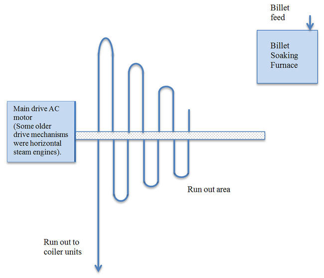
Using a heavy duty, roughing mill stand (often driven by a powerful horizontal steam engine) the fast reduction of a suitably heated large ingot or slab direct from the reheating furnace into a suitably heated elongated slab of a suitable length to feed directly into the closed coupled four/five stand finishing mill became possible as briefly detailed below Originally multi in line four/five stand hot steel rolling mill electric drive requirements were based upon an Ilgner set drive system which consisted of a large high power AC motor driving coupled in line with a large heavy flywheel and one, two or more DC generators. The number of generators used matched the number of rolling mill stand drives. The development of DC motors for mill roll drives has become almost standard practice due to the flexibility in the ease of speed control and reversibility.
Cold commissioning of any multi in line four/five stand hot steel rolling mill is not a very exacting task, primary it requires the checking of all the electrical equipment and generally ensuring that mechanical alignment with the roll stand gear boxes, but not the operational use of the ingot reheating furnace and the alignment with the initial roughing mill stand and run out tables and their availability for incorporation into the entire mill train.
At SCOW the power drive system which had been adopted was not based upon the Ilgner power transfer system and control theory because all five main mill driving motors were to be supplied by rectifiers and the inter acting magnetic effect with respect to operational load and stable speed recovery is almost impossible to duplicate under varying load conditions. By using a rectifier source of DC energy instead of the well-known Ilgner system there were always speed/load problems. Subsequent operational testing of the five-stand close-coupled rolling mill unit could not be tested and proved to be operationally acceptable.
The Basis of the Ilgner System The Method of Energy Transfer
An Ilgner set drive system consists of a large, high voltage, high power AC motor driving, coupled in line with a large heavy flywheel and one, two, or more DC generators. The number of generators coupled in line matching the number of rolling mill drive motors, and dependent upon the control method preferred and the control system power source generator.
Description of Energy Transfer
The Route of Energy Transfer is based upon the fact that an AC main drive under constant load conditions can be designed to rotate at a specific speed and the rotating energy supplied from the kinetic energy stored in the fly wheel will, under an initial power surge such as occurs when the hot ingot, slab or other form in which the steel is being reformed enters the rollers of the mill, cause an abrupt increase, mill by mill stand in the power required by the Drive motors of the mill stands. This additional power requirement in turn creates a slowdown of the DC generators of the Ilgner set, which being solidly/mechanically coupled to the AC motor drive and flywheel causes both of these items to slow down. The slowing down, giving up some of the inert energy in the fly wheel acts to prevent, to a certain extent, the restricted slowing down of the Ilgner Set group until the control systems of the component parts can adjust to the new power requirement and the disturbed power requirements of the main AC motor drive returns to its rated speed.
However it must be recalled that the energy requirements in any multi continuous rolling / reduction process is additive and whilst taking place over 10 to 20 seconds has increased linearly the voltage surge on the AC motor drive which will not recover as quickly and could often take as long as 2 to 3 times depending upon the recovery capacity of the main high voltage power system and voltage source.
In these earlier days most electric control systems were based upon a time frame controller operated through magnetic/electric coupling which due to the effects of hysteresis is not instant and has its own time factor and no matter what occurs a time factor will always incur an increase in any control circuit based upon Mag Amp type of control.
This phenomenon has always been one of the setting up of any continuous rolling mill systems where multi stand in line DC drives were/are in sequence or where additional power is required in the format of additional rectifiers acting as the power booster source. In the past similar switching surges. For example a 30 MW, 3 phase wind power tunnel fan drive if switched direct into a 400 MW grid system caused large system swings and was still causing problems when the system was upgraded to 800 MW by the addition of a 2 x 200 MW of generation capacity within 15 miles.
Ceylon
At SCOW the majority of the cold commissioning was complete and any further interesting work appeared to be a long time in the future. During lunchtime discussion a colleague mentioned that I might be interested in a position as an engineering inspector with the FOC in Ceylon, which he understood, would shortly be available. FOC was an acronym for Fire Offices Committee, whose head office in those days was in Watling Street in the city of London, financed by the Insurance and Assurance companies whose underwriters provided the finance for compensation with respect to general goods and fire damage insurance cover to their clients world wide.
The knowledge of the engineering inspectors and their reports were expected to cover almost every engineering discipline as applicable to commercial warehouses, factories and industrial premises and with special references to engineering plant maintenance and overall safety and the special fire risks and the state of the protection being provide as associated with tea factories.
My application resulted in an interview, during which I was asked if I would be willing to undergo a short period of intensive training in fire protection theory and the application of fire prevention techniques and equipment before taking up a position in Ceylon. The training I undertook and factory visits I made must have proved satisfactory as some weeks later I found myself en route to Ceylon by sea with two other young men, a recently certified chartered accountant and a junior tea planter and three women, all nurses going to work in Ceylon. This was in 1950.
During the sea journey I had the good fortune to make friends with the chief engineer who beat me at chess regularly but from whom I also learnt many gambits to improve my game. In those days the rigours of our Health and Safety Act were in the dim and distant future and his invitations to the engine room and explanations of the detailed workings of the mechanical and other engineering parts were both fascinating and instructional. The engine room required constant supervision, twenty four hours per day while the vessel was at sea, and the operation was so integrated with the loading and un-loading of cargo that a considerable portion of the crew would be classed today as multi-tasked and definitely earned the title of Able Seaman.
One of the most interesting visits to the engine room, the details of which I have never forgotten, included a secondary visit to the driving shaft tunnel. This is a section of the ship housing the long, massive, thick steel drive shaft that connected the main propulsion unit to the external propeller, accessible throughout its length for inspection purposes. On the Warwickshire the shaft was at least thirty-six inches thick, assembled from a number of forged steel sections, flanged and bolted together to make up the required distance from engine room to the stern of the ship. The shaft actually twists in operation, this twist is constantly measured and monitored by a simple optical device projecting a line of sight through the shaft between a fixed point fitted to the stable and driven end of the shaft and a further fixed point (scaled) when the shaft was stationary. When the engine delivers power to the shaft and the shaft begins to turn the propeller resistance causes the torque in the shaft, which in turn causes, a twisting action throughout the shaft length.
My ten-minute discussion with the chief engineer during this particular visit increased both my knowledge and understanding of various theoretical and practical aspects of power transmission. Nowadays, with the adoption of electric drives coupled with Pod technology for the power drives of large marine vessels, the distance between the engine room and the propeller is covered by the use of electric cables, long heavy steel shafting is no longer required, and the engine room can be located in the most convenient section of the ship to meet the owner’s requirements with regard to its operational duties.
On arrival in Ceylon I undertook further training with the local resident inspector for the Kandy area. Upon completion of the training I moved to Dickoya which became my base and where I was to stay, except for periodic visits to Colombo, for the rest of my tour. The work involved travelling widely throughout the various tea growing areas of the eastern and central parts of the island. The work and the writing of reports consisted of 80% repetitive inspections primarily of the safety and security of the mechanical and electrical equipment and generating installations at tea factories. During my 18 months in Ceylon I increased my knowledge of small to medium diesel and gas engines (10-100hp), including the now extinct hot bulb diesel and gas engine. I also increased my knowledge of small to medium (200 kw -1,200 kw) Francis, Pelton and Kaplan hydroelectric turbines and pressurized water sprinkler and other fire fighting systems for tea factory protection.
Two other inspections are worth mentioning. The first involved the commissioning of No. 1 Laxapana Hydro-electric station (3 x 8.5 MW Pelton wheel driven hydro-electric units and overhead transmission system). This stage of the work was followed by the completion of the testing and energising of the high voltage overhead line to Colombo. The completion of the first phase of the Laxapana Hydro Electric scheme provided the much needed additional electric power for further industrial development in Colombo and the surrounding district. This, together with the implementation of phases two and three and the clearing of virgin jungle areas to the central north of the island for the proposed Gal Oya Hydro Electric Project Site would, when completed, greatly reduce Ceylon’s dependency upon imported fuels.
The second was a government inspection, which involved reporting on the total collapse of the steel work supporting the roof structure over the cement kiln at a cement plant. The original design parameters allowed for a nominal build up of cement dust on the H and T angle sections but included clear instructions that weekly checks on dust build up were essential. However, the local contractor had changed and reduced the cross sections of steelwork originally supplied and had persuaded the owner to agree to these changes. He had also omitted to check the level of dust build up during the first few months of operation and remove any excess. The inspection and report showed that the dust had not been removed, it had built up and in the high humidity in Ceylon and the enclosed space had hardened into a thick layer of cement on the steelwork. The resultant weight increase had caused the supporting structure to collapse and the death of a number of workers. This whole experience was one that still causes me anger and distress to this day.
Warrington - The commissioning of a Morgan Rod and Bar Rolling Mill at Lancashire Steel
I returned to the United Kingdom from Ceylon in 1951 and married my wife (one of the nurses I had met on the boat going out) and rejoined The English Electric Company at their Stafford Works in the Metal Industries Section as a contracts engineer. The work involved the general and commercial management of contracts directly associated with the electrical drive control systems required for the various types of rolling mills for the production of ferrous and non ferrous semi finished products. The work with respect to the integration of the technical requirements and the transfer of data between the various technical and manufacturing departments required to meet the contractual dates was interesting. However, after the first six to nine months, it became in the main repetitive and rather boring.
Up until this time my work had mainly involved many and varied electrical and control system installations. In this work with English Electric I was required to be ‘on call’ and available to visit within 24 hours should any problems arise. I also learnt that when you were involved in a turnkey type of operation, such as those within the Metal Industries section, the client considered you represented the company in all aspects of the work, not just the electrical aspects.
It was at about this time that the Metal Industries Section was asked to provide the services of a specialist on-site installation and commissioning engineer to oversee and bring into service the entire electrical control systems, mill drives and high voltage switchgear and transformers for a Morgan Rod and Bar Rolling Mill at Lancashire Steel. I applied for the position, my experience and technical knowledge were considered appropriate and I was lucky enough to be given the post.
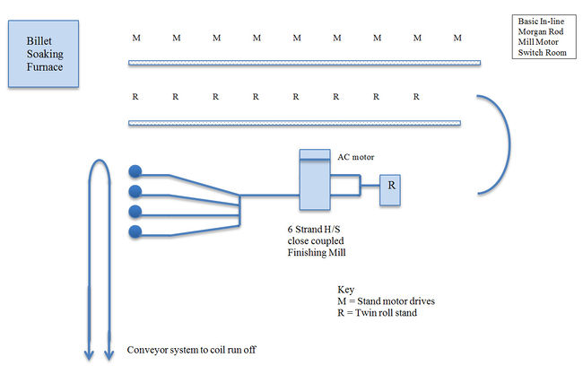
I use the word lucky for two reasons, the first reason was that I had recently completed my first project with Metal Industries which was to coordinate the technical data and requirements and prepare the commercial orders for a similar mill installation which the company had obtained for A/S Norsk Jernverk, a new Norwegian Steel works being built at Mo i Rana just south of the Artic Circle. Few engineers get the chance to follow a project from its commercial specification to completion in the field, which is what the work at Lancashire steel would involve. The second was that the contract was for the supply and installation of all the electrical equipment, commencing with a new high voltage substation to feed the two six phase transformers each of which in turn fed a bank of three rectifiers to supply the necessary DC power for the mill drives, and to assist with commissioning in association with company representatives. The mill would be the first sixteen stand Morgan Rod and Bar Rolling Mill worldwide to be controlled and fed from two groups, each group containing three six phase grid controlled rectifiers.
Briefly the faster the distortion (using 16 sets of roll stands in close tandem in this instance) is performed the less overall energy is required to achieve the required reduction of the hot steel mass to the dimensions and requirements of the finished product.
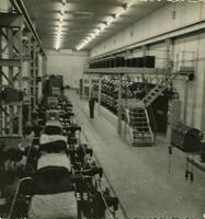
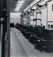
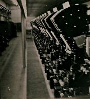
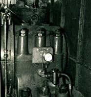
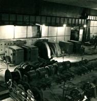
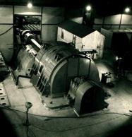
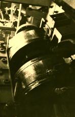
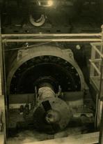
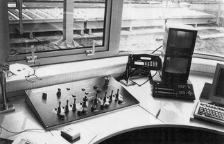
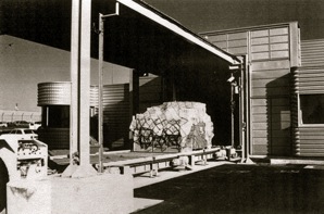
The following photographs show the main motor room, rectifiers, switchgear, control systems and main motor generator. A similar, but smaller, generator and series of control circuitry contained the necessary equipment for the finishing coiler drives and conveyor equipment.
However in achieving the first stage reduction at speed A the length of the hot material entering into the second stage B has notably increased and to prevent hipping of the very hot and still malleable metal entering stage B the rolling speed of stand B has to be increased (or the roll diameter must be increased which for a number of practical reasons is inadvisable) The process is repeated at each stage from B to C, C to D, D to E, and E -F. From stand F the elongation of what is then a dull red very hot length of steel strip is traversing the half-mile run out tables to the coiler stand where, although still hot, it has adequate flexibility to be coiled into a large roll of sheet steel.
During the initial field-testing of the equipment and the circuit testing and circuit proving running of the equipment it soon became obvious that this contract was without doubt a first in its field. While the individual parts, such as the two power transformers and their inbuilt voltage step control systems were almost standard pieces of equipment, the various AC and DC motor drives and their direct speed control drives, when overlaid with the variable voltage control system for the rectifiers which was meant to raise and lower the thirteen mill motor and four coiler drive motor drives in unison, were a nightmare of errors waiting to happen.
The problems of cold commissioning and specifically the loading problems experienced by the multi-phase rectifiers when dealing with the shock loads that occurred during the hot steel rolling and forming cycle which I had previously found during the cold commissioning work at SCOW were reoccurring on the multi-stand Morgan Rod and Bar Rolling Mill. The general problem was that the different equipment coming from various English Electric factories had never been matched up as an entity and in some instances had not arrived on the work site in accordance with the original delivery programme. As a result testing was carried out ad hoc, inter system design proving was an impossibility.
Our first problem arose with the ball and roller bearings of the two motor generator sets. These were the first items to be test run and, although the machinery and circuitry were quite simple, it became apparent during the initial day to day running of the first machine (to prove the direct current output stability required for the control circuits of the main mill drive switchgear) that both the ball and roller bearing got quite hot. When we started on the circuit testing of the second motor generator set output we found we had the same set bearing problems.
At this point we encountered a further problem; namely we could not stabilise the motor generator set direct current output voltage with the designed variable speed range required for the coiler drive motors. After four days testing and plotting and resistance calibration we managed to get a near voltage speed match from the coiler motors. Unfortunately the Lancashire Steel on site chief electrical engineer, was not happy with the appearance of the fire bars suspended on the wall behind the control cubicles of the coiler drives. Privately I agreed with him, however, I had by then a much greater problem. The ball and roller bearings on the second motor generator set had packed up completely.
A further hitch occurred during the overall coordination checks of the coiler systems when we attempted to integrate the coiler cooling pit fan drives into the operational sequences necessary to ensure that the coiled rod was cool enough to be swept off the cooling stands onto the moving conveyor without distortion.
Each of the four coiler units had a separate, high speed, centrifugal cooling fan manufactured by Keith Blackman. However, when we attempted to start up the fans, the motors cut out on overload before reaching half of the designated fan speed. Checking the fan design details against the horse power and motor speed details it became clear that the motor was grossly underpowered and something required correction and quickly, as the efficiency of rod cooling was an essential element for maximising output in an automated mill of this type.
This was a major problem repeated on all twelve of the main direct current motor drives of the six roughing mill stands and six intermediate mill stands and, as the drives were similar in all respects, with the exception of the operational speed ranges I am still inclined to believe it was an original factory problem that had occurred due to manufacturing delays which meant the machines were rushed through the factory test bays (although they were still delivered to site late).
Electrically the machines appeared to be in operational order when we first turned them over on the lower speed ranges. However, as we took them up to full speed we noticed that the bearings were starting to run hot. We stripped down the first electric drive motor, blued the bearings and found that, not only did the white metal show any signs of scrapping or bedding but, the white metal and the shaft bearings showed clearly that they had never been matched or checked for the correct bedding either after manufacture or on any test runs that may have been carried out. Due to no fault of our own we then had twenty-four white metal bearings that were suspect and required attention and four sets of motor generator bearings that were suspect.
I was working on the calibration of the rectifier voltage control circuit in which an intermittent and annoying fault had materialised which, from time to time, caused sudden, and at that stage in the testing programme, totally unexplainable voltage surges to occur with occasionally extremely bad effects on the high speed DC circuit breakers.
During the overall preoperational run up test of the mill there was a loud explosion and the entire mill sequence shut down. The DC switchgear was a new design specially for use with large rectifier loading and multi-drive DC machines. We found that under certain conditions when both banks of rectifiers were connected in parallel this occurred. Unfortunately the circuit breaker completely disintegrated. It occurred eight times, eventually we were told that the arc blowout coils had been incorrectly designed. In the photographs of the machine hall the rather large arc shield can be seen.
By this time my weekly reports from site consisted of a long list of manufacturing items that had given problems or were suspected of or already showing signs of faults. My monthly progress reports to Stafford had been classified as undiplomatic. However, after a site visit and subsequent report from the Manchester engineer, whose report was apparently more scathing than mine of the problems which had been allowed to develop at the site, I was asked to report to Stafford and present my list of faults in a meeting which was to include representatives from the manufacturing divisions involved in providing materials.
An interesting metallurgical fact, raised during the investigation of the various problems that had arisen during the commissioning period and apparently not generally known to store keepers at that time, was brought to my attention during two site visits made by representatives of the ball and roller bearing manufactures SKF and Ransome and Marles. After examining the bearings they stated that they must have stood for some considerable time on end instead of being stored flat. Further investigation revealed that, some time previously, the stores department of the works responsible for the manufacture of the motor generator sets had reorganised their stores area in an effort to maximise the shelf storage and that by stacking the ball and roller bearings on edge more could be accommodated on a space for space ratio and the packages were more easily accessible!
During my time at English Electric I was primarily involved in the installation, testing, commissioning and putting to work of steel and non-ferrous rolling mills at a time when the industry was changing from the use of Ilgner DC generator and flywheel systems for DC production to the use of rectifier supply DC systems. This meant that I was involved in work at a number of different mills. These included:
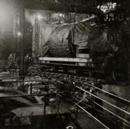
- a five-stand DC rectifier fed booster fed strip mill at John Summers in Wales.
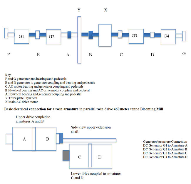
- a blooming mill (2+2 armature twin DC drive) Ilgner set at Aciéries de Longwy, France.
- a plate mill owned by Colville in Scotland, (see photograph)
- a five stand strip mill in Belgium,
- a blooming mill at Consett in County Durham, England
- a blooming mill in Sweden and
- the 16 stand rectifier fed Rod and Bar Mill at Mo i Rana in Norway.
Each mill experienced different electrical control system problems and presented different electrical, mechanical and civil engineering challenges.
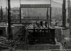
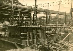
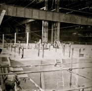
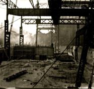
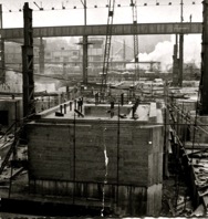
The Aciéries de Longwy project was the most interesting and comprehensive project that I undertook for English Electric. My responsibilities commenced from the design stage cross checking civil and foundation installations, testing, and checking for the 400 metre tonne twin armature in parallel twin drive. For the Aciéries de Longwy mill I was also involved in the overall civil engineering work required in the preparation and alignment of the holding down bolts and foundations for the mill drives. The following photographs show the various stages of my involvement from the positioning of the twin foundation blocks and the exact precise location of the foundation bolts (32 foot long bolts) to the pouring of the foundations and the final installation of the equipment and testing one year later.
Note: each drive motor had 20 x 4.5 inch diameter holding down bolts (8 x 32 foot long and 12 x 36 foot long) all of which were actually prepositioned vertically and braced to permit a single mass concrete pour. There was only one deviation from the vertical of five-eights of an inch.
Sittingbourne and Kemsley
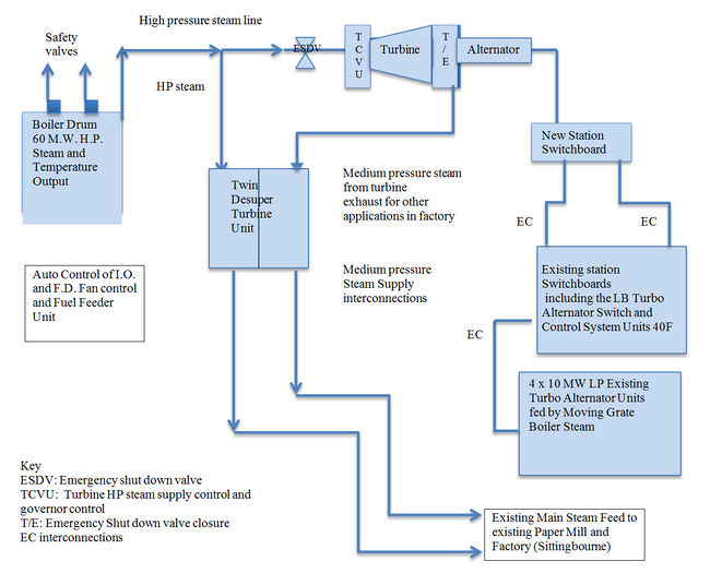
I left English Electric to join Ewbanks and Partners at Bowaters for the testing, commissioning and bringing on line of a 60 MW modern power station, complete with the steam supply on the emergency shut down and a new high-speed newsprint paper mill. Briefly the system was designed to bring the existing paper mills, boiler plant, power plant and low-pressure steam system up to date in line with a completely new Power Plant. This was to consist of a 60 MW boiler capable of producing steam (at temperature and pressure) to feed the HP section only of a standard normal 60 MW turbine generator set. The calculation being such that the exhaust steam at a lower temperature and pressure could be controlled to feed into the existing low pressure steam lines feeding the paper mills and the three old 10 MW turbo generators.
The Turbine shown above consists of the High Pressure to Mid Pressure section of a Conventional 0MW to 60MW Turbine Unit - 3 Stage. Unit: coupled to a 30MW Alternator Generator Unit.
In effect the new HP Turbine and 30 MW Alternator were to be used as a pressure reducing valve - the exhaust steam (calculated as being equivalent to approximately 30 MW of power).
Note: The electrical output from the new 30 MW Alternator was designed as a suitable free standing system primarily for the new high speed modern paper mills and new 60 MW BOILER ancillaries with suitable cross connection to the existing/old switch boards.
During the design stage an emergency requirement had been necessitating the introduction of an emergency shut down valve for the New Turbine unit. It appeared to have been necessary in addition to the normal requirements. From my dry testing circuits and checks it appeared to comply with the stated requirements however, as I detailed in my report, during testing and commissioning calculating the temperature and pressure and rate of the HP steam flow if it is stopped suddenly (that is the emergency valve closes) was virtually impossible. If 30 MW of electric power is cut off as is the flow of LP Steam reduced to the paper
mills, the 60 MW Boiler cannot immediately close down, there will an immediate rise in boiler pressure, resulting in all the boiler safety valves blowing.
My testing report was submitted and during a visit I received shortly after from my electrical director I was informed that the mechanical director thanked me but I could rest assured that such an occurrence could not or would not happen. Later at lunch he implied that the senior electrical director was in total agreement with me and that instrument and control circuitry should always be checked and commented upon.
There was a sequel to the contract, the client or at least some person with doubt regarding the efficiency of the system asked for the operation of the emergency valve. About six months later in Canada I received a letter from Bernard, my assistant at Kemsley, which stated: ‘Arthur today I sat in the sun and watched the greatest display, perhaps ever, of the effects of a 60 MW Boiler letting off steam; taking your advice, when I was told that the Emergency Shut Down test was to be carried out, I retired to the end of the jetty’.
Canada
In 1956 I was seconded to the newly opened Toronto office of Ewbanks and Partners to assist with the initial design and project work for the new thermal power station being built in Estevan, South Saskatchewan and to follow up on the installation, testing, commissioning and putting to work of the primary high voltage switchyard, cooling water pumping station, low and medium voltage switchgear and with specific reference to the coal handling, extraction and delivery system. It may be worth noting that we introduced the Hue Wood safety system for conveyor controlled circuitry which after testing was accepted at the Boundary Dam site in Estevan and subsequently by the province of Saskatchewan as the preferred conveyor safety control method. My wife, daughter and baby son joined me after about 6 months and we soon moved from Toronto to Estevan. The work was interesting and informative but we returned to the UK for family reasons.
Willington Power station near Derby
When I returned from Canada in 1960 I rejoined English Electric to oversee, test and check the electric, hydraulic and pneumatic instruments at the Willington No. 2. with 2 x 200MW output. No. 1. with 4 x 100MW was having trouble with the voltage variation and stability of the power transformers feeding each of the boiler ancillary drives.
The work required during commissioning and putting to work was interesting and informative with really only two electrical/mechanical problems. One problem was the starting time required for the emergency feed pump, this was too long, it was a 2,500hp AC motor switched directly onto the 11 kV start-up switchboard. Of course this caused an immediate voltage drop that was reflected in the operating voltages in the remaining 3.3 kV and 480 volt switchboards, all of which were supplied from the station 11 kV system. This fault was easily corrected; it was calculated during the cold testing, the run up time against low back pressure being over 15 seconds and extrapolation showed that at full steaming collapse it approached 30/40 seconds plus. The second problem was that the coal handling conveyor system electric control relays (on some of the long distance units) had been supplied with normal contact operating coils instead of high impedance coils resulting in the non-activation on some of the longer routing conveyors. These problems were simple to correct but difficult to pinpoint in the multi-control system of long and complex coal conveyor systems.
However, the control/operating problems on the auto/control of the coal crusher feeders, ID and FD fans were found by very patient analysis, and had been evident for over two years from commissioning until the station superintendent refused to take over the fourth 100 MW boiler system and by implication the other 3 boiler systems until he was supplied with a satisfactory solution and the matter corrected. I think the solution is worth describing in view of the facts. Simply the efficiency of a large boiler depends on two basic systems acting in conjunction; one the condition and amount of fuel being fed and burnt in the furnace, two the amount and rate of air (cold and hot) flowing into and through the combustion chamber (ID and FD fans). All the AC drives (2ID and 2FD and 4 feeders) had to be provided for, each controlled by a suitable tapped and variable output transformer. We had 2ID and 2FD and 4 feeders, a total of 32 transformers in the control systems of the 4 boilers. ID induced draft fans/FD induced fans, motors and transformers were identical in size, speed range and output.
Our testing programme took nearly six months and was thorough and the power station staff were most helpful. They had to meet the grid requirements and at the same time meet our requests to change the operating mode of the boiler to meet our requirements for the tests. This meant they had to manually compensate for the errors that occurred during switching. The results of four different loading/unloading tests separately on each boiler were inconclusive. Not only were speeds not the same between any two ID and FD fans but the variation in the outlet pressure differed. The solution came late one evening when my colleague and I were sitting comparing four sets of test results and our calculations in preparation for a meeting with the station superintendent. We compared all the readings from one set of boiler tests against each of the other three, and while never finding a direct one to one balance, we did locate a similarity in the aggregate of two of the boiler units which, when cross-checked, led us to the assumption that there was some form of fault in each of the control transformers although these were not necessarily causing similar reactions to each boiler drive group.
We concluded that we had to tell the station supervisor and his colleagues at the meeting that it would be necessary to strip one of the control transformers to examine it for possible wrong connections of an indeterminate nature. The next morning I was called to his office to meet the director and chief engineer of the boiler manufacturers. I explained our conclusions. The station supervisor informed the manufacturers that No 1 boiler was being shut down for its annual check and that I should choose a transformer and he would have it shipped back to Laurence Scott and Electromotors (the transformer manufacturers) for a complete works test and examination. The director and chief engineer agreed. It was also agreed that all interested parties would attend a meeting on the Monday morning. Just before 10 o’clock on the Monday the chief engineer of the company that had designed and manufactured the units phoned and asked if I could cancel the meeting. On the Sunday afternoon when the transformer was opened it was clear that five of the twelve tapping connections had fractured. I was fully aware that the braising of copper wire to flat copper bar, often used by some manufacturers, tends to cause embrittlement at the joint because the wire will vibrate at a different frequency to the bar within the transformer casing.
Many years later a client, (La Porte, a manufacturer of chemical products which require the use of high speed, high pressure air flow which in turn usually requires the use of a 1500hp - 2000hp three phase motor) contacted me. His only grid supply was totally inadequate being a 6.6 kV three-phase overhead line. I was asked to suggest a possible manufacturer and suggested they contact Laurence Scott because they were considered experts in designing and making double and triple wound large squirrel cage motors.
London and Tokai Mura
In 1962 I moved with my family to London. I was working for a large consortium of companies on the Tokai Mura nuclear power station in Japan. This was the first overseas turnkey contract completed by a British consortium in conjunction with an overseas government. The management structure of the project was rearranged to include a director, a chief engineer and an operational manager. The operational engineering section consisted of a nuclear engineer and physicist, a mechanical engineer and an electrical engineer. I was offered and accepted the position of electrical engineer; it proved to be one of the most interesting and informative four years of my career; not only did I discover the extent of my own knowledge but also the importance of detailed forward planning, accurate shipping and manufacturing programmes and the control of the various company representatives within the consortium and government authorities. The five individuals worked together as a team with responsibility to and for the project rather than to the individual companies. The project was making a loss when the new management team was formed. Getting it back on track was a challenge. There were multiple issues. For example the top cap retaining ring structure had been omitted and the building superstructure had been completed without the necessary civil works.
London and Rustfya
I was headhunted by Rustyfa and worked with them as a project manager from 1966. During this part of my career I was involved in the application and management of the various engineering disciplines connected with security design, and the financial, banking and other requirements involved in conducting international negotiations to obtain multi-million pound engineering contracts for the manufacture, supply, shipping, erection, testing and production of a range of end products for two tyre factories in Bulgaria and Rumania.
These projects enabled me to broaden my electrical and mechanical engineering knowledge, and provided me with a sound working appreciation of the associated chemical manufacturing technical practices needed to produce the required end products. This included the various mixes required to produce a wide range of suitable compounds which in the production of a tyre involves both high and low pressure steam, hot and cold water, and the control systems for the control sequences critical to the reliability and safety of the end product.
It also enabled me to develop a more through working knowledge of the management expertise required including: how to provide an effective interface for the control of the seven consortium companies of the group; how to engage in the international financial discussions required to ensure the smooth operation of the various bank accounts particularly with respect to invoice clearance, and the importance of correctly detailed, packed, verified, costed and shipped items FOB or CIF as appropriate.
Wolverhampton and GKN contractors
In 1969 I was headhunted again, this time by GKN and offered the position of proposals manager, the fourth member of a management team that was being recruited to form a new sub group within the company called GKN Contractors. The aim was to exploit the knowledge and experience within the other GKN sub groups. My remit was to use the vast amount of existing specialised technical knowledge, (industrial, manufacturing, financial and contacts) in all aspects of the iron and steel manufacturing and finished product industry to work on and develop a series of proposals.
The first major product that I was asked to coordinate was for a small steelworks to be constructed in Rio Grande do Sul, Southern Brazil. The client’s consultant for the project was BOFORS, a Swedish Group and one of the world authorities in the production and manufacture of special steels. I engineered this project to a successful turnkey contract including negotiating and arranging the initial financing for all the equipment, from ore preparation to the finished product of a merchant section special steels production facility. This was achieved with the assistance and cooperation of the suppliers (GKN and BOFORS) of the special items such as ore preparation kilns, electric arc furnaces, and multi stand rolling and forming equipment. Total equipment financing values of over 11 million pounds were involved including all delivery charges to C.I.F. Porto Alegre, Rio Grande do Sul.
Our original remit from the company for GKN contractors was to show promise on our start up finance based on a spend of £200,000 within the 1st year. In the event we achieved over £10 million during our 1st year and were in negotiations for a further £1,200,000 for earthquake shook proof level luffing cranes and workshop equipment for a dry dock facility in Valparaiso Chile. Within 5 years GKN contractors had become a major player in the sale of our services in Eastern Europe and South America.
A return to London and to electrical and mechanical engineering
It was some years later and when GKN Contractors were well established that I was approached by the senior partner of an established Saudi Arabian engineering group with a list of project proposals, including all electrical and mechanical work associated with the completion of extensions to the Al-Masjid Al-Haram mosque in Mecca, the security systems for the three new projected major airports, and a section of four medium sized diesel electric power generating stations and local distribution systems in the more remote and developing parts of the Kingdom.
From our discussions it emerged that the senior partner and his partner, a brother in law, already owned a profitable agency working throughout the Kingdom, and which was already working with MAN, a highly reputable German manufacturer of medium to large diesel engines, Phillips, an international supplier of lighting equipment, X-Ray equipment and electronic systems, and five or six other reputable agencies in addition to operating three small jobbing Electrical and Mechanical Contracting companies in Jeddah, Riyadh and Dhahran. They wished to enter, and were receiving government encouragement to do so, the field of large turnkey contracts which were available within the Kingdom.
It was the end of 1977 and I had been considering the idea of starting a small private consulting practice in my own name. I was offered two long term retainers for my services by this group on the understanding that I would agree to be available for an agreed amount of time as required each calendar year but not exceeding twenty days in total. After a visit to Saudi Arabia and further discussions we agreed a trial method of working in which I would act as a consulting engineer on any matter to which they directly referred me and in which I was experienced.
This work broadened my experience greatly and my interest and knowledge of security systems, methods of X ray examination, lighting systems and glass technology were greatly enhanced during the ten years I spent as an engineering consultant. I travelled extensively world wide during this period. I briefly describe the scope of my work below which included researching and engineering, negotiating, witness testing, supervising installation and hand-over to the client.
- The entire chandelier contract and all the internal electrical work for the Al-Masjid Al-Haram mosque.
- A number of medium sized diesel generating stations and distribution systems for small townships and remote areas based on the turnkey basis of design, build, test, staff and operate, tender and contract.
We secured five of the contracts on our tenders including:
- Generators, Power Transformers & Switchgear from Siemens
- Distribution Transformers shipped from Ireland
- Wood poles cut, dressed and shipped from South Carolina, USA
- Chandeliers from Glass Export in the then Czechoslovakia
- With the assistance of Philips (the industrial x-ray section at Marwah, USA) we secured the contract for the first complete passenger baggage handling and x-ray examination system based upon fluoroscopic screen technology for the then New International Airport being built in Jeddah.
Arising from the successful installation of this system we were requested to investigate the viability of a similar system for the examination of 20 and 40 foot ICU Containers for possible use at Jeddah Port. From past experience I already knew that the technology was available and that the use of high energy MeV Accelerators had been successfully applied in the internal examination of large and complex metal castings, the major issue was obtaining a clear definition of the contents of the containers.
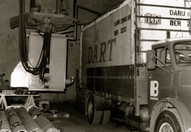
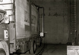
At that time I was witnessing a series of high voltage cable testing at the Balteau high voltage test laboratories in Liège, Belgium during which I discussed the outline of my ideas for the examination of the contents of ICU Containers and the difficulty of locating a suitable testing facility to prove the operational feasibility. During lunch one day Balteau indicated that they had a rather old Vickers 4 MeV Accelerator, which should have the necessary energy level, and in conjunction with Balteau I assisted in formulating a feasibility study using high energy MeV Accelerators and fluoroscopic plates for imaging the detailed definition of ICU container contents.
The concept of X-ray examination of ICU containers is now over 40 years old. The original experimental research was carried out in Liège, Belgium by a company specialising in the manufacture and supply of high voltage equipment and fluoroscopic screening for industrial and security examination units. I prepared and gave one of the first presentations on the subject to his excellency Dr Fayez Badr in May/June 1981 as a possible solution to port congestion caused by the necessity of unpacking and repacking of all ICU containers passing through the port of Jeddah prior to the importer taking title of the container and its contents.
I designed and registered the first UK (and subsequently USA) patents on an integrated container system on the 8th July 1982, these were granted 3rd September 1986 with a priority date of 23rd September 1981. (Reference UK patent number 2110037 and US patent serial number 456111 filed 6th January 1983). It is from these designs that the modern installers/contractors systems were developed by Schlumberger and later Heimann.
With the exception of the advances in electronic imaging techniques the original concept described in the above patents has not altered. The apparent delay in the progress of the concept to industrial operating unit was due to the non-recognition of the versatility of the system and the apparent high initial cost. Of the three companies listed below, one of whom did the original work, they either concentrated on the electronic systems required or assumed that the overall approach to the problem was such that the solution lay in adapting the existing X-ray examination technology as applied world-wide to passenger baggage handling. It must be remembered that in the early part of the 1980s even the X-ray examination of aircraft hold baggage was considered both uneconomic and impractical.
Note: Balteau was taken over by Schlumberger who sold that part of the business to Heimann. Heimann was subsequently absorbed by Siemens and are now a company within Smiths Detection, a division of Smiths Group plc. They installed under the name of ‘HI-CO-SCAN’ or ‘SYCOSCAN’ at least 10 systems worldwide. Subsequently, due to government legislation and commercial pressure and significant advances in technology, processing and data analysis, modern imaging systems (both fixed and mobile) have been developed and installed at entry ports, border crossings and for the examination of rail freight world-wide including the identification of contraband, drugs and illegal substances.
The 2 photographs show the 4 MeV UNIT suspended from an overhead crane on one side, alongside an enclosed van containing an assortment of goods, liquids, boxes and crates packed with various smaller and odd shaped items free standing, and on the other side of the truck suspended from the other side of the overhead crane the frame that held the picture plates. Due to the high-energy emission from the MeV UNIT, all personnel had to be excluded from the warehouse in which the test was to be carried out.
Two types of test were carried out:
The first was with the van at standstill and the overhead crane controlled remotely to move over the length of the van. The viewing results:
- First traverse - cloudy and distorted but recognisable (believed due to vibration)
- Second traverse - item definition/recognition clear (crane at steady each take)
The second set of tests were repeated under the same conditions but as 2 second traverses at three different energy levels giving compatible and encouraging results for Balteau, Schlumberger, the two representatives from the French customs authority who witnessed the tests and me. As far as I was concerned the tests and the observations of all these parties justified my application for UK and USA patents.
Schlumberger went on to obtain the contract to build the first X-ray Air Craft Cargo examination unit for Orly Airport Paris. The following photographs show the system at Charles-de Gaulle airport.
Although I am now well into retirement I try to keep abrest of developments in the field. In 0ctober 1994 in response to Region 8 Director (Professor C W Turner’s) appeal for surplus IEEE publications needed by Libraries in East Europe I arranged for copies of my journals to be sent to engineers in Lithuania and Bulgaria which I continued to do until quite recently. I have developed my interest in renewable energy sources, which has included a visit to a solar power facility in southern Spain, the presentation of a paper on wind power generation at the IET Renewable Power Generation Conference in Edinburgh in 2011 and last year I visited a research station near Oxford which is exploring the use of fusion. In July 2012 I was invited to attend the 50-year celebration of the founding of the UK and RI section of the IEEE and in 2014 I was invited to attend meetings of the Council for the IMechE.
I have had a varied life as an engineer and am passionate about the profession I decided to join. Although I was originally an electrical engineer I have also learnt a lot about mechanical engineering and also about civil and chemical engineering. I have been able to travel extensively as part of my work and seen many amazing places as well as meeting many interesting people. The work, the people and the places have all contributed to my life-long learning which continues today, albeit at a slower pace.
