First-Hand:My Ten Years at Ampex and the Development of the Video Recorder
Contributed by: Fred Pfost
Introduction
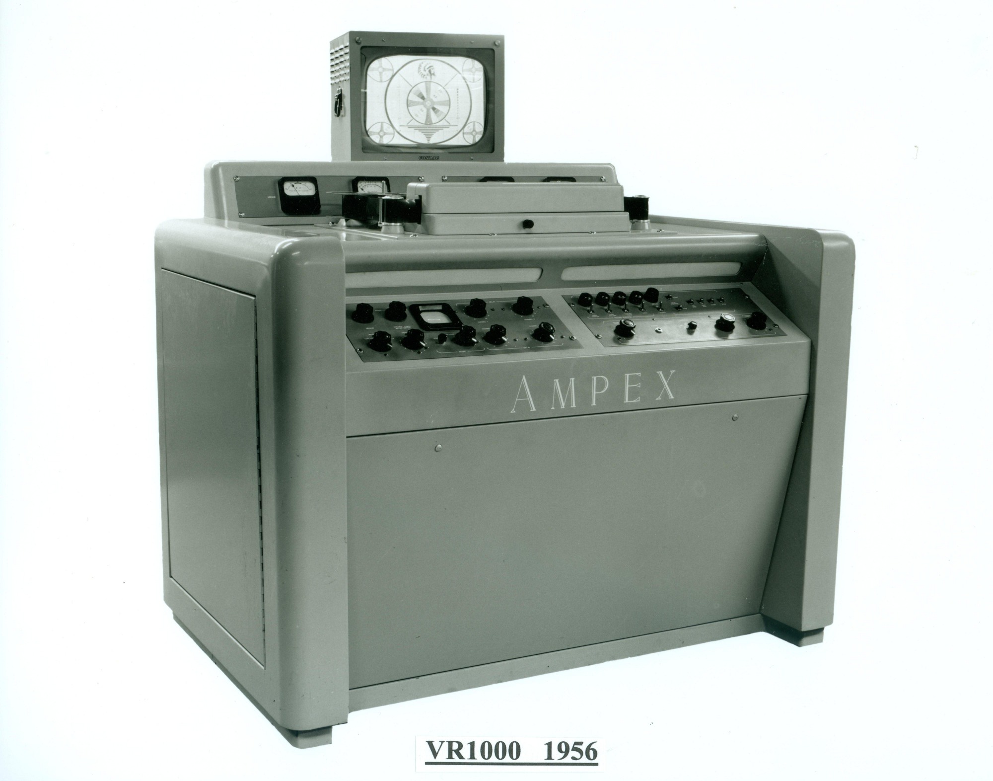
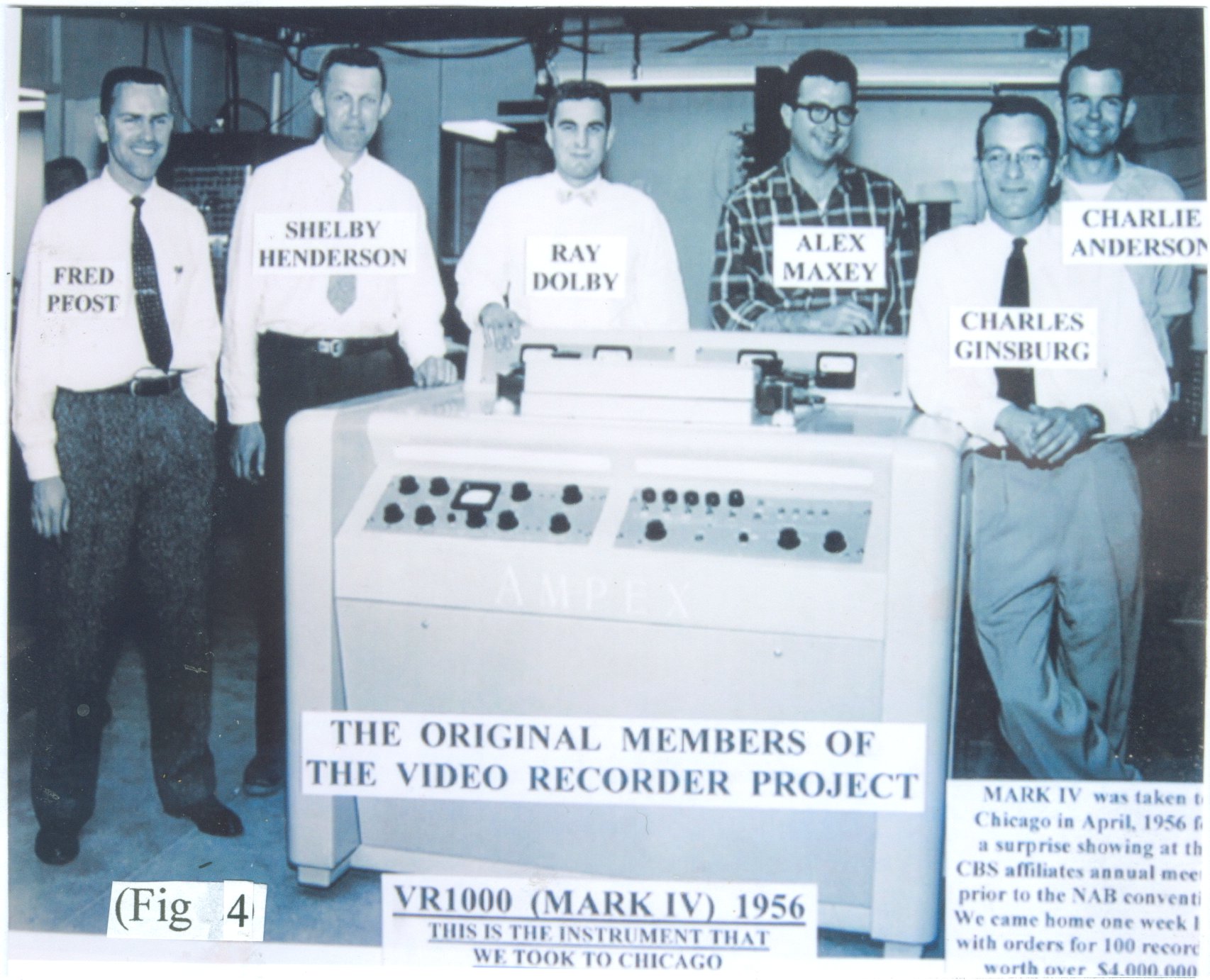
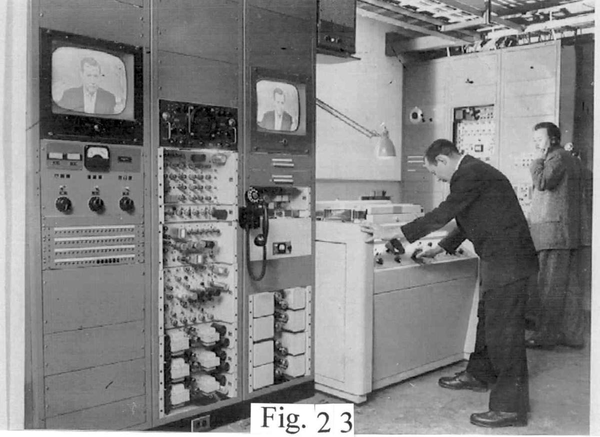
When I first started working at Ampex on February 4, 1952 (4 days after my last final at The University of California in Berkeley, California where I earned my bachelor of science degree in electrical engineering) I spent about a week being introduced around the company to various people and departments including the president, Alexander M. Poniatoff, who had started the company in about 1944 near the end of the World War ll. Ampex had been manufacturing small electric motors to drive radar antennas but found it necessary to find a new field to pursue after the war. This turned out to be audio magnetic tape recorders. By 1952 Ampex led the world in producing professional audio magnetic tape recorders. Almost every radio station in the world used Ampex professional audio recorders. It would be four more years before AMPEX's introduction of the world's first economically and technically successful magnetic videotape recorder the VR1000 (affectionately called the Mark-4 video recorder). (Fig. 1)
FM Recorders - My First Assignment
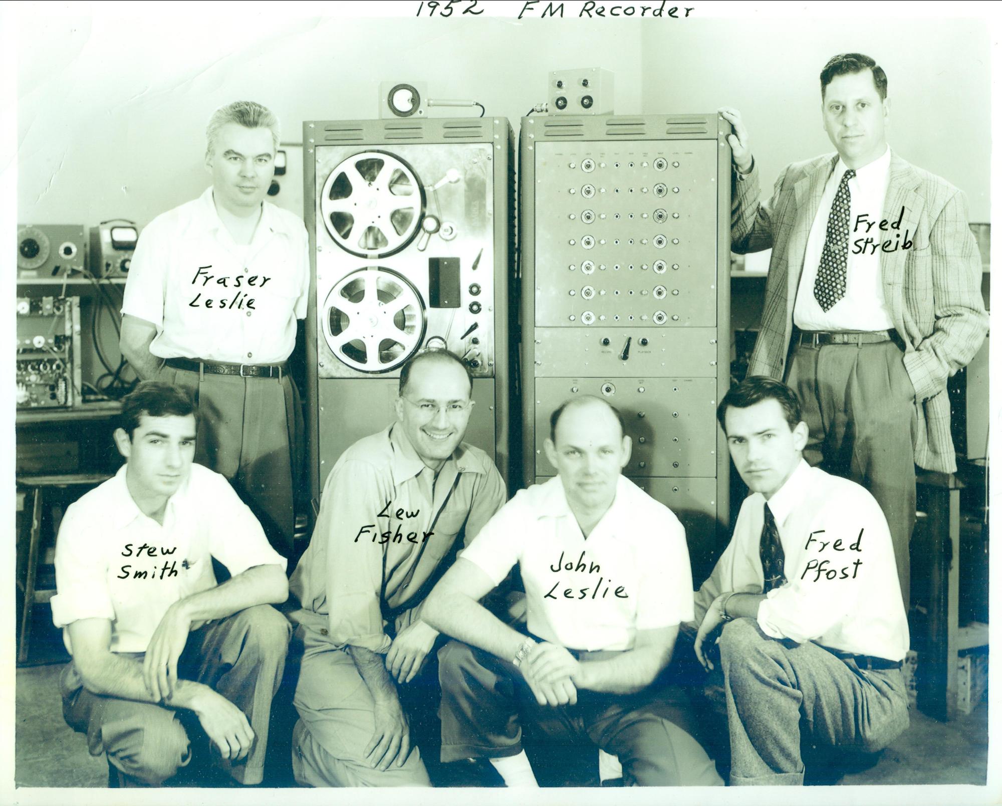
My first assignment at Ampex was to work on the assembly of the electronics for a product line that Ampex was just beginning to get into - FM recorders for data recording in the field of instrumentation. After about four months this project was transferred to the manufacturing division.
I was then assigned (along with my boss, Clarence Stanley) to develop a 21-channel instrumentation recorder for the Navy. We modified a standard Model 300 top plate and designed and built the record and playback electronics for the 21 channels. I built a mechanical switching device to switch, simultaneously, between record and play for all 21 channels. This 21-channel recorder project took eight months. I then designed and built and delivered to Texas an oil well logging recorder. I designed and built a flux-sensitive playback head (for this recorder) to use on the rotating, magnetically coated, 12-inch aluminum disk that could read from DC to several hundred Hertz. This recorder was built for Perforating Guns Atlas Corporation in Houston, Texas.
Next, in these interesting and actually exciting projects, I was assigned to assist one George Berttell in the development of a complementary amplifier/speaker unit whose amplifier was equalized to compensate for the loudspeaker's falloff in the low- and high-end frequencies. This unit was to be used in conjunction with a semiprofessional audio recorder (whose final electronics assembly I had made). This recorder was named the Model 600 and the amplifier/speaker unit we developed was named the Model 620. They were mounted in matching, portable, light brown Samsonite cases. (Fig 2)
Thousands of these systems were sold and they established the standard in the marketplace for this class of audio systems. In September of 1954 I was assigned to the Video project that had been restarted in August to further evaluate the feasibility of recording television on tape. Several other companies had developed recorders that were totally impractical and unsuccessful. A few of these were RCA, GE, Crosby Enterprises, BBC and Siemens GmbH. Ampex had hired Charles Ginsburg in June of 1951 to manage the video development along with Ray Dolby (who was still a student at Stanford and worked for Ampex just part time) and Shelby Henderson, a machinist. Within a year they had developed a rotating head recorder mechanism that, when used in conjunction with some 2-inch wide audiotape from Minnesota Mining and Manufacturing Co. (3M), (Fig. 3)
had produced some fairly encouraging results. However, at that time, a pressing requirement developed for an audio project (in the movie equipment field) that exhibited a higher priority than the video project, so the video project was put on the shelf temporarily.
First Effort at Video Recording
When the video project was restarted in September of 1954 it was composed of Ginsburg, Dolby, Henderson and some new members: Charlie Anderson (hired in August), Fred Pfost (transferred in September), and Alex Maxey (transferred in October). This group became the team that continued on through the completion of the first videotape recorder demonstration (outside of the lab at Ampex in Redwood City) in Chicago in April of 1956. (Fig.4)
Scalloped Outputs Require Automatic Gain Control
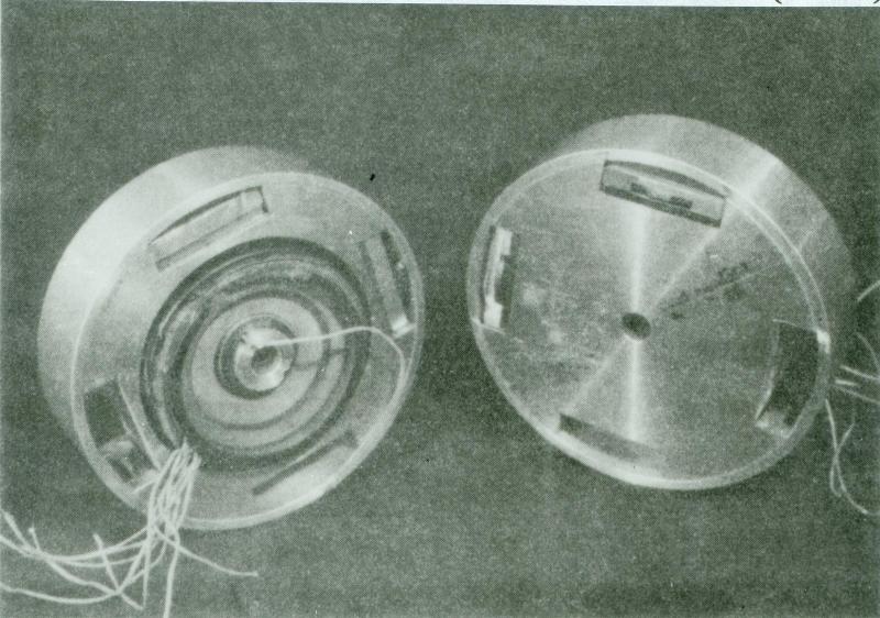
I was initially ask to develop an automatic gain control circuit to overcome the amplitude variations we were getting off tape using the recorder that had been developed in 1951-52 by the first Ginsburg group. This rotating head drum was about two and one half inches in diameter and it initially had three recording heads (transducers) equally spaced around the periphery on one face of the disc. The three were tied electrically in parallel. (Fig 3) The number of transducers around the head drum was increased to four shortly thereafter, with diametrically opposite transducers tied together electrically. (Fig 5) This was in order to feed the signals off the tape sequentially from the four transducers into a two-channel preamplifier.
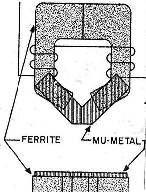
An engineer, Duane McQueen, in the engineering head department in 1951 had made these transducers. They were composed of ferrite cores with Permalloy pole pieces to establish a gap that would ride against the tape to write and read the magnetic signal. (Fig 6) These parts were bound together with epoxy andÿmounted in the head drum with a metal strap around the outer edge to restrain the parts from flying out due to centrifugal force. (Fig 3 & 5) The head drum was turning at 14,400 RPM (240 revolutions per second) with a head to tape speed of 1500 inches per second. That gave a centrifugal force of 3000 Gs at the drum periphery.
Arcuate Sweeps
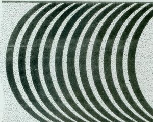
Now let's look at the cause of the major signal amplitude variations that were being observed off the tape. This was a big mystery until we determined the reason. These variations consisted of higher output near the tape edges and lower output at the middle of the tape. We observed that the arcuate shape of the transducer path as it crossed the tape (Fig. 7) had a slight longitudinal component near the tape edge and only a transverse direction near the middle of the tape. We then recalled that the 2-inch wide tape, made by 3M, was manufactured for audio recordings. Audio recorder transducer gaps are usually orientated to write magnetic signals in a longitudinal direction along the length of a tape. In order to give a higher output from a playback head, the oxide particles on tape can be "oriented" in the longitudinal direction. (These oxide particles are acicular in shape about 5 to 1 ratio between length and width. With this orientation, the output off tape will be about 3 dB greater for longitudinally orientated head gaps than if the oxide particles were not orientated (i.e. random orientation). Therefore, one could find a 6-dB difference in output if the gap orientation and the tape oxide particle orientation were at right angles to each other. We, therefore, asked 3M not to orient the tape particles (just random orientation). This should have eliminated the transducer's major output variations that we had been observing. However, there were other, more subtle, negative considerations associated with the arcuate head tracks that influenced us to drastically change the head drum orientation. We modified the head drum orientation by 90 degrees (making the drum surface at right angles to the tape). (Figs. 8 & 9) The axis of the head drum motor would now be parallel to the tape and the path of the transducer across the tape would be almost perpendicular to the motion of the tape. As we suspected, the major output variations we were observing before disappeared and my original assignment of developing an AGC circuit was eliminated.
My Radical New Head Drum Design
Maxey had been assigned the job of developing a new transducer design and he had continued with the ferrite core and Permalloy tips design held together with epoxy. With this new head drum orientation there was no strap around the drum periphery to overcome the centrifugal force on the transducers and his epoxy heads flew apart.
While I was working on the AGC circuit I was mulling over a new transducer design that would be able to overcome the huge centrifugal force at the drum periphery. I described this design to Ginsburg and he liked it and put me in charge of the video head development.
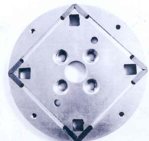
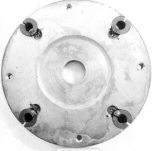
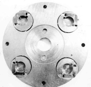
This design was based on the idea wherein I would bury the transducer tips in grooves cut in a disc with only the very ends coming together to form the gap at the disc periphery. (Figs. 10 & 11) Four round (donut shaped) wire-wound ferrite cores were buried in the matching, machined disc (Fig. 12) that was bolted to the first disc.
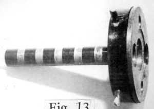
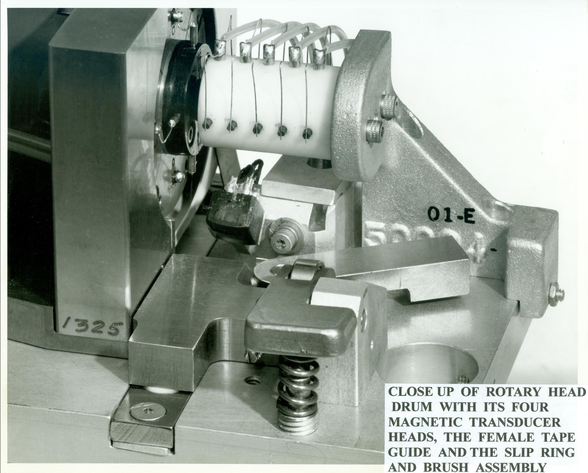
I assembled four transducers on a disc (Fig. 11) and using a slipring assembly I designed and had made (Fig. 13) I fed the head outputs to four separate preamplifiers. I was able to show this assembly could withstand the centrifugal force and could produce good outputs. It was now early December 1954 and I was able to record and play back usable signals as high as three megahertz. This was the highest frequency we had ever seen off tape (and could very well have been as high as anyone in the world had ever seen off tape).
It was difficult (if not impossible) to machine the grooves accurately enough to cause the four gaps to reside at exactly 90-degree locations. I machined the grooves into little discs (I called them dimes) and mounted these dimes in depressions machined into the disc. (Fig. 14) Now these little dimes could be rotated and clamped in the right angular position and held with epoxy to place the gaps at almost exactly 90 degrees.
The next modification to this design was to make the depression that located the dime, deeper and the dime thicker (now called a nickel) so I could mount the ferrite core and the tips in the same piece. This made it possible to check out each complete transducer assembly separately before mounting it into the drum.
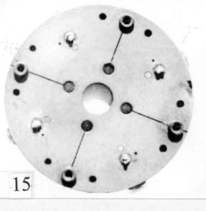
I found some new head tip material, Alphenol, (from the Naval Research Laboratory in Washington D.C.) that had about the same permeability as the previously used Permalloy, but it was much harder and it extended the head life from around ten hours to about one hundred hours. I changed the head drum material from naval brass to stainless steel and cut four radial slots in the drum which made it possible to adjust the 90 degree position of the head gaps to within a few micro-inches of the absolute 90 degree position. This was accomplished by adjusting tapered setscrews located in each of the four slots. This made it possible to record with one video head assembly and play that tape back with another assembly (interchangeability). (Fig. 15)
To give an indication of just how accurate the 90-degrees between gaps had to be, I will put some numbers into the consideration. Our head-to-tape velocity was about 1500 inches per second. In one microsecond a head gap would travel 1500 divided by one million = 0.0015 inch. On a 21-inch monitor the horizontal lines are about 16.8 inches long and this distance is covered by the electron beam making the line in 53.5 microseconds. This calculates out to be (16.8/53.5) = 0.314 inches per microsecond of gap travel. So if the 90-degree position of a gap were off by 0.0015 inch there would be an offset in the picture (when one head is switched to the next head) of 0.314 inch and this would be totally unacceptable. Let's say we could accept a displacement on the television screen of 0.01 inch when the head outputs are sequentially switched into the picture. This would require a gap placement accuracy of (0.01/0.314) X 0.0015 = 47.8 microinches. Using the tapered setscrews it was possible to adjust the position of the gaps to less than this allowable error.
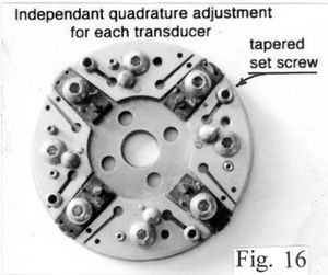
This was the video head design we used in manufacturing for a couple years (1956 - 1958) until a modified design for easily adjusting each transducer quadrature setting
separately, independent of the other three transducers, was made by John King. (Fig.16) John also designed a four-segment rotary transformer to replace the slip ring assembly that could wear out and tended to introduce a little noise in the signal. This was the state of the development by the middle of December 1955
.
The Final Design Gets Built
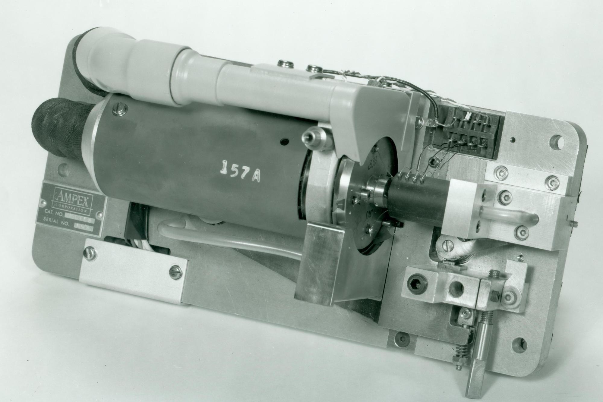
On yellow tablet paper, I laid out the design of the complete video head assembly including the motor, the female tape guide, the timing ring and the associated electrical plugs, which made it possible to easily mount and remove the assembly from the recorder top plate. A good friend and design draftsman, Nick Lasarev, converted my rough sketches into working drawings and Shelby Henderson, our machinist, made the assembly parts on which I mounted my head drum. (Figs. 17 & 18) The output of this assembly gave us the best signals off tape we had ever seen.
New Signal Electronics
Now the signal electronics represented the limiting feature in our system. Right from the start of considerations of the electronics for the video signal (by Dolby in 1951), it was known that a modulation system would have to be used because of the wide frequency range in the television signal (60 Hz to at least 4 MHz). Charlie Anderson was assigned this task and he worked with the amplitude modulation system. The signal amplitude variations off tape at the writing speed we were using (1500 inches per second) were significant. To these variations one had to add the different outputs from the four separate heads on the head drum. These amplitude problems resulted in undesirable amplitude variations in the demodulated signal.
In late December of 1954 Anderson suggested to Ginsburg that a possible solution to this amplitude problem might be to use frequency modulation. The major difficulty one might expect to find in using FM would probably be from the restricted frequency response we were getting off tape. The carrier frequency could not be much higher than the modulating frequencies of the TV signal but by using vestigial sideband modulation it might be successful. He was given the go ahead to do some experimenting in January of 1955. He used a high frequency carrier and modulated that with the video signal. Then, using a heterodyning process, he was able to produce the lower frequencies that were compatible with the recording capabilities of our tape system. He had his system ready for experimenting off tape by the end of January, 1955. The results were very encouraging.
At about this time Ray Dolby returned from his 2-year tour of duty in the army. He had been drafted when he lost his student deferment after he dropped out of school to spend full time on the video project. He now returned to his studies at Stanford and again worked part time at Ampex. He looked at Anderson's FM system and thought he could develop the frequency modulation using a simpler circuit. He took two high frequency radio tubes and connected them together as a multivibrator oscillator. This way he could run the multivibrator at a carrier frequency that was within the bandpass of our recorder and frequency modulate this carrier directly by feeding the composite video signal to the control grids of the oscillator. This scheme worked well and was considerably simpler than Anderson's circuit. By the 25th of February Ray was making better pictures than Anderson so this became the final circuit concept for the FM system.
On March 2, 1955 we gave a very convincing demonstration to the Ampex Board of Directors. We indicated that we could be ready for a public demonstration within a year. We had to repackage all the electronics. We also had to tie down the head drum, the transducers, and the whole video head assembly to manufacturable designs. Also we had to design an attractive package for this machine that was going to sell for a lot of money.
Anderson set about designing the new console that would contain all of the signal electronics, motor drive amplifiers, tape control servo electronics, power supplies, control panels, meters and the tape deck. The electronics were mounted on the inside of four large doors that could swing open for maintenance work. The dimensions were approximately five feet long by four feet high and three feet front to back and weighed somewhere over 1000 pounds when fully loaded. (Remember, this was the age of vacuum tubes and large transformers.) The whole cabinet was painted a beautiful white. When finished this design was dubbed Mark IV. (See Fig. 1)
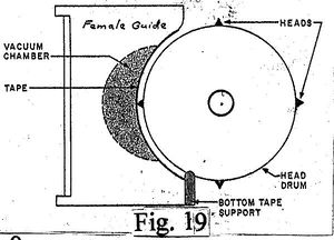
Maxey did some important experimenting with tape tension and female guide position to control the picture distortion and timing. (Fig. 19)
At about this time, Maxey started to design and build what were to be Ampex's first efforts at moving from the quadrature configuration to a helical scan configuration for video recorders. Alex was quite successful with his efforts and within a little over a year he was ready to show what was deemed the Model VRX8000. This was shown to a few potential buyers and put into limited production. (Fig. 20)
Dolby worked on the modulation system by moving the FM carrier frequency to six MHz in order to increase the video frequency response. Ray also changed the head switching circuitry from a two-channel system to a four-channel system compatible with the new, separate, four head outputs from my video head assembly. He also modified the head-switching circuit to place the head-switching transients in the horizontal blanking interval. It was not until after the Chicago showing in April 1956 that he designed and built the processing amplifier for the recorder. He and Ginsburg got together with Bill Lodge of CBS to work out the requirements for this processor. Its purpose was to massage the video and audio signals from our electronics to make them compatible with all the broadcast standards of the day.
On April 16, 1956 (a Monday) we demonstrated the Mark lV recorder at an NARTB convention (National Association of Radio and Television Broadcasters), today renamed the NAB (National Association of Broadcasters), at the Conrad Hilton Hotel in Chicago. On the Saturday before the convention started (April 14) we demonstrated the recorder for about 300 CBS affiliates meeting at the Conrad Hilton Hotel. I recorded (from behind a curtain) the opening speech of Bill Lodge, V.P. of CBS, who described all the activities that CBS had been involved in during the past year and that he had a big surprise to announce. After I rewound the tape and pushed the play button for this group of executives they saw the instantaneous replay of the speech. There were about ten seconds of total silence until they suddenly realized just what they were seeing on the twenty video monitors located around the room. Pandemonium broke out with wild clapping and cheering for five full minutes. This was the first time in history that a large group (outside of Ampex) had ever seen a high quality, instantaneous replay of any event. My wife, JoAnn, who had accompanied us to Chicago (as a reward from Ampex for her patience during my long overtime hours pursuing this development) and I consider this demonstration one of the most exciting experiences of our lives. The experience still brings tears to my eyes when I recall this event.
The predecessor of Mark lV, named
Mark lll, (Fig. 21) was prepared for a press demonstration in Redwood City at the same time as the Chicago event. This presentation was also a huge success.
The Mark IV recorder was moved to a second floor room in the Hilton Hotel and continued to operate flawlessly to a packed room for the entire following week. (Fig. 22)
Orders were signed for about 100 recorders at $50,000 each during that week. This represented an amount almost as great as a year's gross income for Ampex. It was decided to make the first 16 recorders in the engineering division while the manufacturing division geared up for the long run to come. The first unit to go on the air was from CBS Television in Hollywood, California on November 30, 1956. The program was "Douglas Edwards and the News" and as far as we know, this was the first time in history that any videotaped program had been broadcast, nationally, any place in the world.
By the end of 1956 the 16 hand built units were nearing completion and the manufacturing division was pretty well tooled up for the long run to come. I helped them develop some of the tools and fixtures for the video heads and the head assembly. This precision part of the recorder was very difficult to manufacture and there were many "rejects" in the final checkout of head assemblies. It was difficult for manufacturing to keep up with the required inventory of head assemblies for new recorders being shipped let alone the requirements for renovating worn out assemblies as they would come back from the field. (Remember it took three video head assemblies for each machine shipped.)
At about this time the instrumentation division of Ampex (The video recorder development was done under the auspices of the audio division.) was starting to respond to requests from the field for wide band instrumentation recorders. This higher frequency range (1 to 10 MHz) was beyond the high frequency capabilities of the instrumentation recorders being manufactured at that time. The logical solution was to utilize this capability of the video recorder. A major problem arose when it was realized, as mentioned above, that the audio division could hardly keep up with building the required number of head assemblies for the video recorders they were producing, let alone the increased number that would be required if wideband instrumentation recorders were to use the same head assembly design.
A management team of about five members including the V.P. of research, Walt Selsted, and V.P. Harold Lindsey was assembled to find a solution to this problem. It was decided to put a new head development group together to design a completely new head assembly for instrumentation. It was also decided, initially, to use my head drum and head assembly design and just design a new video transducer. Bill Frost was brought in from England to head up this new group. He had been instrumental in the development of the BBC recorder named "Vera." Two other engineers were chosen from the instrumentation division along with a machinist and I was contributed to the group from the audio division. Frost decided that initially, for three weeks, each engineer should lay out three designs for the transducer (for a total of twelve designs). Then the management team would chose the best three designs (#1, #2, and #3).
Following that, our engineering team would work on #1 until it was finished and successful; or, if that one did not succeed we were to work on #2; and if that did not succeed we were to move on to #3.
At the end of the 3-week design period we all met with the management team and each of us engineers explained (with drawings) his designs. As it turned out after the management team made its choices: #1 design was mine, #2 design was mine, and #3 design was also mine. Of course this made me very happy but when we returned to the lab, Frost said "Pfost, you go to work on your #1 design and the rest of you come with me and we are going to work on my design." Of course, this was not the procedure the management team had directed us to do.
After a couple weeks or so of proceeding with this arrangement I decided to discuss this with the president of the company, George Long. He listened to my story but said he was probably too far removed from this activity to get involved but he would see what he could do. The next day I was visited by a vice president, Harold Lindsey, who said I was to be removed from the group and sent back to the audio division where I was to continue pursuit of my three designs. The machinist Hank Miluski was also directed to accompany me back to the audio division. Hank was a great machinist and we worked together beautifully on many projects (even after we left Ampex and he opened his own machine shop in Santa Clara). He became one of my best friends until he died some thirty years later. I really do not know what happened to the rest of that group of engineers.
By that time Charlie Ginsburg had been promoted to vice president and one, Larry Wylan (from CBS), had been made head of the "advanced video department." I was now working for Larry and he bent over backwards to give me everything I needed or wanted. He would also come to my lab every day just to be friendly and to talk about the project.
I will describe my #1 design now. I found a new extremely hard, highly permeable material (originally developed in Japan) called Sendust. It was described in a huge book on magnetics (Ferromagnetism by Richard M. Bozorth). It was not easy to machine this material but I developed a process by which two fairly large pieces of the material (0.1 X 0.1 X 0.25 inch) could be machined to size and one surface on each of two blocks ground and polished. With an appropriately thick shim to establish the gap (100 microinches) and while clamping the two pieces together I would braze the two together. Thus, with this recording gap permanently established, the brazed blocks could be cut into many pieces without affecting the gap. (Fig. 24)
This Sendust transducer became the design used in production for about four years. I chose this as my #1 design because I figured it would take less time to develop it than my #2 design, which was an all-ferrite transducer with glass gaps.
I was thinking about glass-bonded ferrite heads by 1955. The January 1954 issue of the Proceedings of the IRE was totally devoted to the subject of ferrites. This was the first time I became aware of the characteristic details (the specifications) of this material. It is a sintered, ceramic, highly permeable magnetic material. It is used in high frequency, electronic induction coils where, because of its very high resistivity, it exhibits very low internal losses due to eddy currents. I immediately thought this might make a great material for use in magnetic recording heads, due to its hardness. Also, it would be good if the heads were to be exposed to high frequency, magnetic recording signals. Of course, at that time, there were no really "high-frequency" signals being recorded, although the high frequency bias used in metal audio recording heads creates eddy current losses. Consequentially, when I became associated with the video project and its megahertz frequency range, ferrite recording heads became an obvious goal for future development work. Other investigators in the magnetic recording field also had these thoughts for audio recorders.
At about that time, Philips (in Holland), was trying to develop glass bonded ferrite heads. In order to bind the two-transducer pole pieces together to establish a stable gap most developers were experimenting with epoxy as the binding agent. Since ferrite is an extremely hard, brittle material (like glass) and because of the abrasive nature of magnetic recording tape, these gaps would immediately start to crack because epoxy did not offer the same support (strength) as exhibited by the solid ferrite. One other drawback of ferrite for recording heads was the porosity of the material. In the manufacturing process called "sintering", finely ground and mixed materials are compacted in a mold under very high pressure. This establishes the desired shape of the part and then it is removed from the mold and baked in an extremely high temperature oven (1600 C to 2300 C) for a few hours after which it is slowly cooled over twelve to twenty-four hours. This causes the fine particles to coalesce and become extremely hard and brittle. However, microscopically speaking, there are spaces between the finely ground particles that are comparable to the dimension of a playback head gap, i.e., in the neighborhood of a few microinches. Therefore, even if the gap problem could be solved one still had the porosity problem to contend with.
I had solutions for both of these problems. If I could find an extremely hard, strong material that maintained that strength and hardness at high temperature (2000 C) I could make a mould out of it and continue to squeeze the ferrite powder material while baking it and close up the spaces between the powder particles. After many hours of searching I found the material. It is titanium diboride. Now, unfortunately, Ampex management decided that I was not the proper one to pursue this approach but that I should describe my idea to an established ferrite manufacturer and let them do it. (Of course, this was another dumb decision on their part.) Two companies, Transtech and Sony, did exactly as I described and although Transtech could not retain consistency in permeability from one batch to the next in production, Sony was very successful and introduced the material (which I had previously named "hot-pressed ferrite") to the world (another "lost opportunity" for Ampex).
All the head manufacturers in the world started using hot-pressed ferrite (they bought it from Sony) after their adoption of my second idea (the glass gap). I thought if I could use glass to bond the ferrite tips together to form the gap it would support the gap edges and wear as well as the ferrite. I first tried using thick deposits of glass in the gap area before bringing the two pieces together at a high temperature, squeezing the excess glass out, and letting the two pieces settle onto the gap spacer material. This was the same process that I had developed for the brazing material. (see Fig. 24) This was successful once in a while but not often because it was not always possible to squeeze enough of the molten glass out of the gap area. An Ampex salesman took one of the successful units on a video head assembly to the BBC in England (surreptitiously) and it didn't come back until it had 5000 hours of running time. The heads were still in excellent condition but the ball bearings were worn out. This was about ten times longer head life than we were getting with Sendust heads and these ferrite heads had at least another 5000 hours of life left on them. We then started depositing 25 microinches of glass on each polished gap surface by means of sputtering and mating the two halves together (with no spacer shims) with great precision at a moderate pressure and about 800 C. (again see Fig. 24) These gaps were always perfect and when the slabs were parted and lapped to the proper track width and wound (as depicted in Fig. 24) they became the most successful video transducers we had ever made. This is the transducer design that every video recorder manufacturer in the world is using today.
I then did experimentation with "air bearings" because, even though we used the highest quality ball bearings available, they would wear out in less than 5000 hours. I used graphite material and a self-pumping air design so they would not require an external air pump. These showed some success but later the engineering department tried externally pumped graphite bearings with great success and that became the standard. This was especially important since ferrite heads could last for 10,000 hours before they would wear out. These air bearings would last "forever".
In about 1965 Dale Dolby, the brother of Ray, who had become part of the video project in about 1958, designed a new video recorder system to use "tape cartridges" instead of reels of tape. This cartridge recorder was totally different from the standard video recorder. The market for this design was short television advertisements or "ads" that might last a few seconds or a few minutes where it was not practical to use a full hour or two hour real of tape. The recorder could hold a few cartridges or many cartridges and could insert "ad" material or sequential "ads" into any long program as desired. This process required the machine to be able to rapidly thread and unthread the cartridge tape around the top plate and this was not convenient with the vertically standing female guide in the way of the rotating head drum. He modified the way the guide was mounted so it could just flop down out of the way during this part of the threading activity and then spring back vertically to hold the tape against the rotating head drum. He also developed four separate rotating transformers that were mounted on a shaft protruding from the center of the head drum. This became, essentially, the final form of the transducer and head drum assembly for the rest of the "Quad" era and was named the Mark X head assembly.
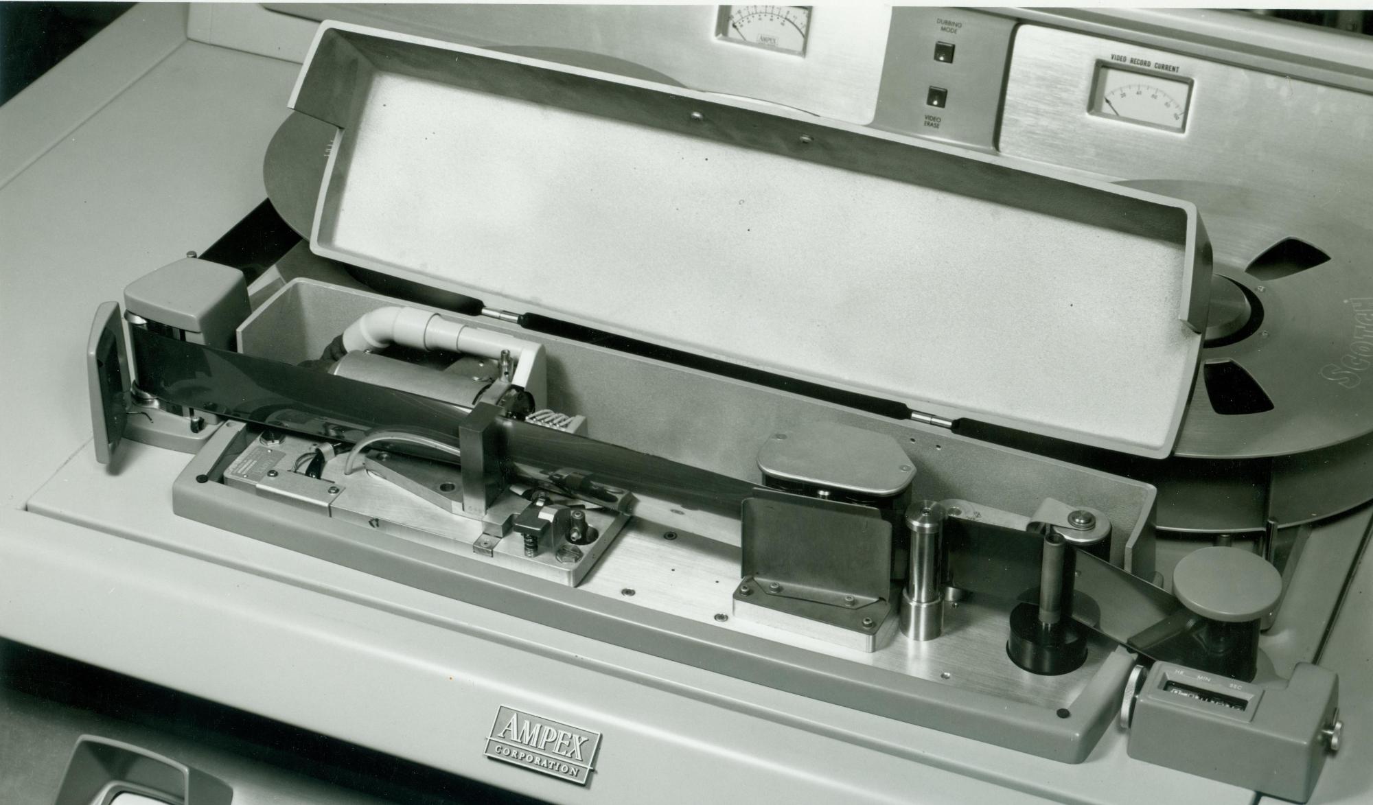
Figure 25 depicts what the final design and placement of the VR1000 audio and video head assemblies looked like when they were mounted on the top plate.
When our videotape recorder was first being used in the field for time shifting to accommodate the various time zones in the USA it became obvious that programs needed to be edited before broadcast just as audio tapes were edited extensively from their first use in radio broadcasting. (At first, audiotapes were cut apart with a razor blade and reassembled in a sequence desired by the director using splicing tape to join the two pieces of tape.) But just how to edit a videotape presented a problem. In order to cut and splice video tape the cut had to be made between two appropriate head tracks (a space of 0.005 inch) and that cut had to be where a vertical blanking signal was located or the resulting picture would be partially of one picture field and partially of another field. (Also because the horizontal pulses would not be timed properly, the picture would "roll," spoken of as a "glitch.") In order to be able to see where the recorded tracks were located we found that a solution of a volatile liquid (e.g. turpentine) with a little powdered iron (called carbonyl iron) evenly dispersed in it and spread thinly over the recorded tracks would allow the iron particles to be attracted to the magnetically recorded tracks on the tape. These tracks were then plainly visible. Now in order to find the proper track containing the vertical sync pulse we recorded a short, magnetic pulse on the control track at the location of the video track that held the vertical sync signal. With a razor blade and a straight edge and a sharp eye it was possible to make the cut. This sounds difficult (or impossible) but this was the method used for years by the industry to edit tapes. Later, we found that powdered stainless steel (instead of carbonyl iron) gave a much brighter indication of the track locations. And, even later, a proprietary material called Ferrofluid made the tracks stand out exceedingly well.
The reason I bring up this whole complicated subject is that I was ask to develop an instrument to automate this splicing activity. I made a transport mechanism onto which one could clamp two lengths of two-inch recorded videotapes that were to be spliced together. (Fig 26)
(Presumably, these two pieces had been cut at approximately the proper place with respect to the program material.) One would cause a slight overlap of the two tape ends at the center of the device and then rotate the two adjustment knobs, one on each end, while observing each electrical meter, one for each tape end, for a maximum output. This indicated that a control track sync pulse was in the right place to make the cut. Then one would rotate the "guillotine" blade to cut the two ends simultaneously in the right position. Next one would pull a lever that brought splicing tape over the cut to gently join the two tapes together at exactly the proper place. In the process of this development I had to develop two flux-sensitive heads to read the stationary tapes tracks.
This device worked extremely well and was very easy to use. However, at about that same time, an all-electronic splicing technique was perfected at Ampex wherein two recorders were used: one to play the first program material and the other to read the second program that was to be inserted into the first. At the proper time the system stopped playing the first program while it recorded on that first tape the information from the second tape. This worked very well and put my splicer on the shelf forever. Therefore it was never produced by manufacturing.
Three interesting sidelight items are as follows: Dale Dolby designed every videotape recorder transport that Ampex made, except for the original Mark lll and Mark lV, including the digital recorders in the later years at Ampex.
Before the Video Project started in 1951 the Ampex marketing department made a short-term prediction of the number of recorders it would take to saturate the American market. The number was 5. When the manufacturing of quad recorders finally came to an end, twenty-some years later, the total number manufactured was 15,000 and the number of head assemblies was 50,000. Of course, this included the overseas sales and also Mexico. The reason for this large number of head assemblies was in order to have one head assembly on the recorder and one backup unit on the shelf and one unit back at the factory being renovated after some part (usually the video heads or the bearings) needed replacement.
In the summer in 1955 Ampex and the San Francisco Symphony Orchestra put on a fantastic program to demonstrate the quality of audio recording instruments of the day. Three very high-quality loud speakers were placed across the stage at the S. F. Memorial Opera House. A model 350 Ampex 3-track tape recorder had previously recorded an orchestral presentation of Mozart's Marriage of Figaro in the opera house. The orchestra assembled on stage and proceeded to play that selection. Halfway through the presentation the members of the orchestra started laying their instruments down until no one held an instrument. Yet, the same music continued to emanate from the stage. It suddenly became clear that none of the music had been generated by the orchestra but was emanating from the loud speakers on the stage. The quality was indistinguishable from the "real thing." Similar demonstrations were repeated over and over where one instrument would play a stanza while being recorded and then it would be reproduced by the audio recording setup. There was no indication of quality difference at any time until there was an effort to reproduce the timpani. During the reproduction effort suddenly, there was an explosion above one of the loud speakers with accompanying smoke. The announcer then admitted that there were still some limits as to the ability to reproduce sounds.
During this entire program Ross Snider, "the voice of Ampex," was announcing the procedures. Next to him on the floor was lying a small Samsonite suitcase with it's lid open and speaker facing the ceiling. Remarkably, this was "my" little amplifier/speaker that George Brettell and I had developed the year before. It - with its 10-watt amplifier and 8-inch speaker - was filling that entire opera house with the loud, clear sound of his voice.
I will add other subjects to this paper as time goes by. Some of these subjects will include:
- a demonstration I made for the Board of Directors to convince them of the amazing effects of stereo sound. (about 1952)
- the 5-channel system I put together for the recording of the movie "Oklahoma." (probably sometime in 1953)
- helping George Brettell with the creation of the famous "Ampex Listening Room."
- a remarkably bad demonstration of the video recorder I made in Los Angeles at a TV advertisers convention in the summer of 1956.
