First-Hand:At the High Speed Flight Station - Chapter 9 of the Experimental Research Airplanes and the Sound Barrier
By David L. Boslaugh, CAPT USN, Retired
Loss of Captain Apt and the X-2
The Los Angeles Times banner headline on 28 September 1956 read “Mystery Plane Crashes in Mojave Desert.” A week later, I reported to the High Speed Flight Station, and my first work assignment was to help in a small group led by Mr. Richard Day, the NACA X-2 project engineer, to make an animated movie of the last minutes of the X-2. This we did with a model of the X-2 mounted on a universal swivel. The instrumentation in the X-2 had survived, and the recorded data had been read out and plotted. From the plots, we set the model at the X-2’s position with respect to the earth and the control surfaces at their recorded positions. This was done every tenth of a flight-second, and one movie frame shot, thus picturing the airplane’s gyrations as it fell to earth.
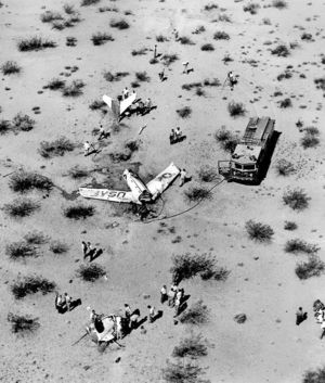
While we were working on the movie, Dick Day told me what had happened. Much to everybody’s amazement, Mel Apt had flown a perfect optimum maximum energy flight profile; regardless of the fact that this was only his first flight in a rocket research airplane. Such skill was just not expected. Not only had his flight profile been perfect, but also the engine had burned 15 seconds longer than expected, resulting in a terminal speed of Mach 3.196, rather than the planned Mach 2.8. Dick was not sure why Apt wanted to start a turn back to the lake bed, perhaps he thought he was getting too far from the base. In any event Apt radioed he was above Mach 3 and starting a turn. Day told Apt, “Don’t turn yet!” At this speed the X-2, at an increased angle of attack in a turn, would have almost no directional stability and would be just as prone to fly backward as forward, and any small rolling disturbance could awaken the roll coupling monster. [36, p.57]
Dick’s radio warning had not been in time, Apt had already started his turn. What they heard next was an unintelligible yell which might have been translated “there she goes,” and then the radio went silent. The film recovered from the cockpit camera showed Apt being thrown around violently in the small cockpit with his head banging the canopy a number of times. The X-2 was completely out of control, falling and tumbling with rotations about all three axes. Apt had apparently been knocked unconscious. It was a repeat of CAPT Chuck Yeager’s wild ride in the tumbling X-1A three years before. The wild gyrations continued down to the denser atmosphere at about 45,000 feet where the X-2 went into an inverted flat spin. The cockpit camera showed Apt conscious and trying standard inverted spin recovery technique, however crash investigation showed he had not unlocked the rudder, which might have made spin recovery impossible. At 40,000 feet, Apt was seen pulling the nose separation handle, and later trying to exit the cockpit. The capsule, however, hit the ground at 120 mph before Apt could get free, and he did not survive. It can be conjectured that if CAPT Apt had been as familiar with the X-2 as Chuck Yeager was with the X-1A, Apt probably would have survived. [8, pp.9-13] [36, p.57] [38]
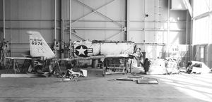
When the nose capsule broke loose, power to the instrumentation recorders was lost, and the X-2 became a totally different airplane. Its center of gravity moved far back because of the missing nose causing it to be tail heavy. Witnesses said the plane then made a series of short glides, after each of which it would stall and start another glide. Dick Day described it as like a gently falling leaf. The plane hit the ground in a wings level attitude and with only enough forward speed to make it slide for about 100 feet. The impact and slide were hard enough to break the fuselage in three pieces, but each piece was relatively intact. Recording instruments in the instrumentation bay were removed with hardly any damage. The remains of the X-2 were trucked to the High Speed Flight Station Hangar and set up on stands for the accident review board. There was some thought given to rebuilding the X-2, but NACA officials decided that the new X-15 research airplane series would be operational in less than three years and could pick up high speed research where the X-2 had left off. I would go down to the hangar occasionally an look at the pieces of the X-2. One of the most dramatic aspects of the wreckage was the charred and blistered paint on the front half of the wings, a testimonial to the power of air frictional heating at Mach 3. [ 8, pp.11-15] [29, p.8] [38]
The Computers
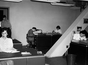
At the High Speed Flight Station in the mid 1950s, if someone said the word computer, they were not usually referring to some kind of a computing device, but rather a human being. The people who worked in the Mathematics Department, almost always women, who read the data from flight instrumentation and turned it into information useful to the engineers, were called “computers.” Theirs' was a vital job demanding utmost concentration and attention to detail, in spite of the possibility that the work could become routine, repetitive and tedious. In December 1946, computing specialists Roxanah B. Yancey and Isabel K. Martin were relocated from the Langley Lab to the Muroc site. X-1 flight testing had already begun, and persons with experience and skill in reading out the raw data from the X-1s instrumentation were needed to translate the data into tables, plotted curves and other standard engineering units. These would then be used by the engineers interpreting flight testing results. The computers work involved use of various formulas to translate deflections on oscillograph films to engineering measurements such as altitude, air speed, control surface deflections, normal acceleration (gs) pitch & roll rates, and wing stresses. NACA seemed to prefer women with mathematical or engineering education for this work because it was felt that men did not have the patience to keep at it. In October 1947, on the eve of the first supersonic flight, the only women in the Muroc Unit were Computing Section head Roxanah Yancey, her two other computers: Phylis Rogers Actis & Dorothy Clift Hughes, and Walt Williams’ secretary Naomi Wimmer. [10, p.128]
Marian and I were married in March 1957, and up to that point, since graduating from Cornell University she had worked, had been self sufficient, and enjoyed working. After a couple of weeks as a housewife, she asked, “Do you think I could get a job at the Station.” I put the question to Phillip Walker, our personnel officer, who replied, “Oh yes, we like to hire employees’ wives because it makes the security clearance process much easier. What is her background?” I told him she had a degree in economics (money, currency, and banking), that she had worked in the actuarial department of Prudential Insurance, and then in the trust department of a bank. She liked to work with numbers. Phil said, “Oh great, math department.” A few days later she was working in Roxanah Yancey’s group, now called the Mathematics Department.
The work was not quite the “working with numbers” that Marian had expected. Each research airplane carried what was called a recording oscillograph as its primary instrumentation recorder. The device was about 20 inches long with a cross section of about 14 by 14 inches, and naturally, it was painted black. It contained a long strip of photographic film about 11 inches wide, and on that film, traces from as many as 36 sensors could be simultaneously recorded as wavy lines. To keep track of time, a vertical line was drawn on the film every tenth of a flight second, and every ten seconds the time from a master instrumentation clock was recorded on the film. Marian’s job was to put the film in a reader where she could see all the instrumentation traces. Then starting with the top trace she positioned a cursor on the trace, turned a rotary switch to identify what sensor she was reading, and pressed a foot treadle to record the reading on a punched card. Then she moved the cursor down to the next trace, and repeated process, sometimes up to 35 more times following the time mark line to the bottom trace. Then she moved to the next time line one tenth of a flight second later and did the whole thing again. She was a machine, and was doing what would today be done effortlessly by computers. After three weeks of this, at supper one evening, she remarked that she realized that she much more liked working with people than working with numbers, and that this was not even really working with numbers; it was dreadfully boring. She wondered if there was some other work she could do, and the next day she put the question to Phil Walker. He thought for a minute and then said, “Marian, there’s an opening in the library, would you be interested?” She jumped at the chance, and that day moved to the library where she loved the work and thrived. More about this later
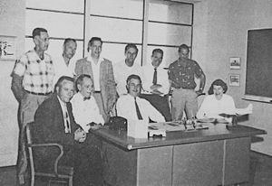
In Chapter 7, we showed a photo of most of the original 25 NACA Muroc Flight Test Unit employees who were supporting X-1 flight testing. As of October 1957, ten years after the first supersonic flight, ten of those people were still at the station. Seated (left to right) - Gerald M. Truszynske, Chief Instrumentation; Joseph R. Vensel, Chief Operations; Walter C. Williams, Chief of Station; Roxanah B. Yancey, Supervisory Mathematician. Standing - Charles M. Hamilton, Assistant Superintendent, Flight Maintenance; Clyde G. Bailey, Superintendent Flight Maintenance; Hubert M. Drake, Assistant Chief, Research; John W. Russell, Rocket Group Leader; De E. Beeler, Chief of Research; Richard E. Payne, Crew Chief.
Pitch-Up and the F-104 Fighter
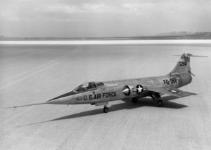
It took only a few days to finish the X-2 movie, and then my new boss, Jack Fischel, called me in to discuss the next assignment. He noted from my history sheet that I had worked with supersonic wind tunnels at the University of Minnesota's Rosemount Aeronautical Research Lab, and that I was familiar with airplane stability derivatives. He wanted me to assist stability and control engineer Ed Holleman in a computer simulation study of the pitch-up problems of the Air Force’s new F-104 Mach 2 fighter. The study would use an analog computer, called a differential analyzer, programmed with the stability derivatives and coefficients of the F-104. The pitch-up problem with the D-558-II Douglas Skyrocket has been described in chapter 10. In summary, airplanes with high-mounted horizontal tail surfaces were generally subject to pitch-up, subsequent high speed stall, and loss of control. This was because the stabilizer was prone to being suddenly pushed downward by wing downwash at high angles of attack. A case in point is the Russian Mig-15 fighter in the Korean War. The MiG-15’s high-mounted stabilizer caused many cases of pitch-up in combat, especially at transonic speeds when shock waves formed on the tail surfaces. American pilots used this weakness by deliberately trying to make the MiG-15 pilot make high angle of attack pull-ups or turns. Doug Dildy writes that American pilots reported at least 56 cases where the Mig-15 went out of control in such maneuvers. In 40 instances the MiG pilot either did not regain control before ground impact, or the plane broke up in the air. [11, p.25]
The Lockheed F-104 had what was called a “T” tail with the horizontal stabilizer mounted on top of the vertical stabilizer. Wind tunnel tests had shown that the arrangement helped alleviate roll coupling problems, but it did make the plane susceptible to pitch-up. To make things worse, when the F-104 went into pitch-up, it usually fell in a gyrating tumble. Many thousands of feet of drop were needed to recover from the tumble, and if initial altitude was not great enough, it could end in disaster. The Air Force had requested NACA to study the problem and propose solutions to help prevent pitch-up. This led to Ed Holleman’s simulator study of the F-104 problem.
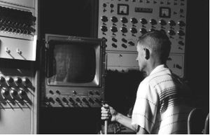
The High Speed Flight Station had a room-filling general purpose Goodyear Electronic Differential Analyzer (GEDA) analog computer that could be programmed to simulate airplane flight dynamics. High Speed Flight Station Engineer Richard E. Day had programmed the analog computer, to simulate airplane flight. By setting the characteristics of a particular aircraft into the computer, the machine could simulate the dynamics of any aircraft. The computer had to solve a number of differential equations of motion simultaneously in parallel to represent flight. Digital computers of the time were not fast enough to do this in “real time.”
My first task was to digest a report on “airplane differential equations of motion.” These were six equations that could be used to describe airplane dynamic behavior in terms of the movement along the airplanes three axes, and rotations about the three axes. They were, in effect, the embodiment of Newton’s laws of motion describing airplane motions in six degrees of freedom. By entering characteristics of a specific airplane such as: weight, moments of inertia, wing area, engine thrust, lift coefficient, drag coefficient, stability restoring moments due to displacements in pitch, roll and yaw (called stability derivatives), moments due to control surface deflections, et cetera, into the equations of motion, one could come up with an accurate mathematical description of the behavior of an airplane in flight. There were even what we called “cross-coupling” stability derivatives such as “roll due to yaw” and “yaw due to roll’ that fed from one equation to another. All of these coefficients and stability derivatives had been determined beforehand from wind tunnel and flight testing.
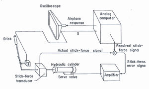
Ed then taught me how to program the analog computer, which was very different from programming today’s digital computers. The analog computer did not deal with numbers as does a digital computer, it dealt with voltages, the final result of which moved a symbol around on a cathode ray tube, representing the motions of the simulated airplane. Fortunately, station engineer Dick Day had already wired up the various components of the analog computer as sort of a general purpose machine that simulated flight in six degrees of freedom. We made our specific settings to simulate the F-104 with patch cables pushed into a plug board, and by turning volume controls on each amplifier to represent the plane’s coefficients or stability derivatives. To represent flight conditions at different speeds and altitudes we would change the volume control settings.
High Speed Flight Station Engineer Richard E. Day programmed the station’s Goodyear Electronic Differential Analyzer, an analog computer, to simulate airplane flight. By setting the characteristics of a particular aircraft into the computer, the machine could simulate the dynamics of any aircraft. Here he is “flying” a simulation of the of the X-2 research airplane. The computer had to solve a number of differential equations of motion simultaneously in parallel to represent flight. Digital computers of the time were not fast enough to do this in “real time.”
Our simulated airplane cockpit had a seat, an oscilloscope display tube, and a control stick. The display tube showed the motions of our airplane as well as a target we were supposed to try to follow. The control stick was connected at the bottom to a hydraulic cylinder. The computer was programmed to have the hydraulics provide normal control feel as the stick was moved, and also to shake the stick to warn the pilot that he was nearing a pitch-up condition. If that didn’t work the hydraulics were to force the stick forward at the instant just before pitch-up occurred. If the stick shaker or stick pusher went off too early the F-104 could lose maneuvering performance which was critical in an air superiority fighter. If it went off too late, it could ruin the pilot’s whole day. Our job was to determine the exact combinations of angle of attack and pitch rate at all speeds and altitudes for shaker actuation that would allow maximum combat performance, but prevent pitch up. We were also to determine the best amount of force when the stick pusher was activated. Finally, when we had determined the right mixture of angle of attack and pitch rate at each speed and altitude combination, we were supposed to estimate combat performance lost by stick pusher activation. To make things a little more realistic, Ed had added a feature that made a warning noise if we went into pitch-up. The sound was like a small animal squealing in pain, and we really tried to avoid pitch-up.
On 4 October 1957 when Ed Holleman and I were well into setting up the simulation, the nation and, in particular, NACA got quite a shock. The Soviets had put Sputnik into orbit. It took only a few hours for our radio technicians to pick up Sputnik’s signal and pipe its beep-beep-beep throughout the station’s hallways. It was a reminder we had better get busy.
We had the system set up and programmed by December 1957, and asked the station test pilots to “fly” the simulator and evaluate its realism. All of them had flown the station’s F-104 chase planes, were familiar with their performance, and thought the simulation was quite realistic. Then we started running “test flights.” When we thought we had the best settings at a particular flight condition, we would ask the station test pilots to fly the simulator to get their evaluation of pitch-up prevention. We would also try different levels of stick pusher force, and they agreed that a forward force of 30 pounds at the grip was best. It took about a year to run tests at all flight conditions, and write the report. NACA released the final report in January 1958. The Air Force later sent a letter of appreciation for the study and said that modifications were being made to F-104 control systems based on our findings.
Marian the Librarian and Copilot
The difference between reducing oscillograph flight test data, and working in the library was like night and day. Marian loved her new job. When she started in the library, there were four other young women assistant librarians, all wives of station employees or military officers assigned to the station. As time went by, however, there was an amazing turnover among the assistant librarians. It was so prevalent they called it “library disease,” but in reality it was pregnancy. In a little more than a year, Marian found herself second in charge of the library, then in the fall of 1948, Mrs. Foley, the head librarian decided to retire. Marian delightedly accepted the offer to take over as head librarian.
On of the functions of the librarian and staff was attending library conferences that rotated among the NACA laboratories, usually about three times a year. For the away conferences, it was usually found that the least cost way of getting the librarians to the conference was the station’s WW II vintage DC-3 utility airplane. The station’s junior test pilot was normally assigned the job of transporting the librarians, and no copilot was assigned. In the case of Marian’s conferences their assigned pilot was always the newest at the station, in this case a young fellow named Neil Armstrong. Before each flight, Neil would announce he needed a copilot to help him. Marian and I were both taking flying lessons at the Edwards AFB flying club, so Marian always volunteered. She not only did things like set the flaps and raise and lower the landing gear, but also took over piloting on long straight stretches, then Neil told her what RPM to hold the engines, what altitude to keep, and the compass heading. She confessed that she never mastered steering by compass, but would pick some landmark like a mountain top and just head for it. There are surely a thousand regulations today that would prohibit such a thing, but things were a little different then. In any event, Marian can say with a straight face that she flew copilot with Neil Armstrong.
The F-107 Project
In late 1954 Air Force General Operational Requirement (GOR) 68 called for a new Mach 2 all-weather air superiority fighter bomber capable of carrying a nuclear weapon. It was to be a replacement for the North American Aviation F-100 fighter bomber. Two companies entered the competition: Republic Aviation with its F-105 fighter bomber, and North American Aviation with its F-107 fighter bomber. In the case of North American, the company was already building three prototypes under an earlier contract for an upgrade to the F-100, and Republic was under contract for 15 F-105s. In each case the manufacturers proposed to upgrade these existing planes to meet the new GOR. In March 1957, the Air Force selected Republic Aviation as the winner, and the USAF was left with three North American F-107s having no future, but having a number of advanced design features including:
- A variable area engine inlet duct programmed to change inlet area in response to changes in speed and altitude.
- Wing spoiler-slot-deflectors for roll control
- All moving vertical and horizontal stabilizers
- Automatic pitch and yaw dampers, and
- An augmented longitudinal control system (ALCS) programmed with speed and altitude inputs to give the the airplane the same longitudinal pilot handling qualities throughout the flight envelope out to over Mach 2 and to 53,000 feet altitude
Most of these advanced features were new to the Air Force, and of great interest to them, especially the bottom four related to airplane stability and control. In mid 1957 the Air Force asked NACA to take possession of two of the F-107s to run a methodical evaluation program on the features, with first priority given to the stability and control aspects. The augmented longitudinal control system was of particular interest because its purpose was to make the plane feel the same to the pilot in all flight regimes. The primary criteria in fighter plane pilot handling qualities was the stick force required to pull one additional force of gravity in a turn or pullout. It was called “stick force per g.” For a fighter, the ideal stick force per g was about five pounds, as adjudged from experience in World War II fighters such as the North American P-51 Mustang or the Supermarine Spitfire. It was also important that the stick force per g remain constant over the entire flight envelope.
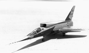
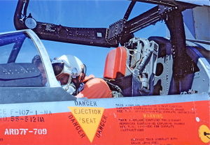
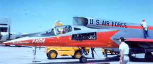
The F-107 also had one other very unusual design feature, its engine air intake was on top of the fuselage immediately behind the cockpit. The plane was to have a fire control radar in the nose that precluded a nose intake as in the F-100, so a chin mounted intake was considered. There were problems here too. The F-107 was configured to carry a streamlined nuclear weapon shape about half buried in the underside of the fuselage, and there was concern that the shock waves from a chin-mounted intake would interfere with bomb separation. Side mounted inlets were ruled out as being incompatible with the desired variable area inlet duct. Having two separate inlets was inviting asymmetrical flows into the engine if the two automatic ducts did not track exactly with each other. The only place left was the fuselage top. This led to a very futuristic looking airplane, but also caused an interesting operating problem. Because the engine air intake was immediately behind and above the cockpit, the pilot’s canopy could not be opened and seat straps unbuckled even at engine idling speed because the pilot could be drawn into the air intake. The engine had to be completely shut down before pilot egress. Some ground crews called the F-107 “the man eater”, but I never heard our pilots complain about it. More about this later.
A North American Aviation pilot delivered the first of the two F-107s to the High Speed Flight Station on 6 November 1957, and the second was taxied up the apron on 10 February 1958. Initial flight tests of the first F-107 revealed reliability problems, whereas the second plane was quite solid, so the first was relegated to being a source of spare parts. Ed Holleman and I had finished the F-104 pitch-up study in January, so I was open to another assignment. In February Jack Fishell called me in and said he would like me to take over the F-107 flight testing project. The main thrust would be to evaluate the effectiveness of the augmented longitudinal control system and the pitch & yaw dampers. We would also measure a number of other coefficients and stability derivatives at a wide range of speeds and altitudes, so they could be compared with wind tunnel testing results.
The natural pitch and yaw damping of an airplane reflects the tendency of the craft’s tail surfaces to resist the angular velocity in pitch and yaw by displacing air from their broadside movement through the air. Consider their damping resistance as being the same as the air resistance of a fast moving fly swatter. Another analogy is the shock absorbers in your auto. One key thing to remember is the damping resistance is directly proportional to the angular pitch or yawing velocity. Some airplanes, such as a Piper Cub have what is called “dead beat damping”, meaning a a quick control movement in pitch or yaw elicits a response to the new commanded position without any hunting back and forth. Some high performance planes, however, such as fighter aircraft have a tendency to hunt back and forth for a number cycles around the desired position before coming to rest. They are said to be lightly damped. Heavily damped planes have a relatively slow response time in moving to the new position, whereas lightly damped craft move quickly, but bounce for a while.
In a fighter airplane, there is an “ideal” compromise between fast response and resultant hunting. What is desired is a few rapidly decaying hunting cycles before coming to rest. The measure of damping is a function of the ratio between the maximum amplitude of one cycle, and the max amplitude of the following cycle; and it is called the damping ratio. The ideal damping ratio for a fighter had been found to be about seven tenths, which is also considered the best damping ratio for most servomechanisms. For a real life example, the WW II Hawker Hurricane fighter had a natural damping ratio of about 0.7, whereas the Spitfire was a little more bouncy. You can’t please everybody though. Some pilots loved the Hurricane because it felt solid and, “All you had to do was point it where you wanted to shoot.” Other pilots though the Spitfire was great because of its quicker response.
Pitch and yaw dampers are automatic devices that sense airplane pitch and yaw rates using angular rate gyros and send signals to the hydraulic servomechanisms moving the horizontal and vertical stabilizers to oppose the pitch or yaw velocity. In so doing, they augment the plane’s natural damping. They are much quicker than a human pilot could possibly be. In the F-107, the damping systems received signals from an analog air data computer that adjusted their quickness of response (gain) as a preprogrammed function of speed and altitude. The preprogrammed gain settings at any particular combination of speed and altitude had been predetermined by predictions of F-107 flight characteristics from wind tunnel tests. The horizontal stabilizer response to stick motions also received gain adjustment signals from the air data computer as a function of speed and altitude. The goal of the two systems working together was to make the plane have directional and longitudinal damping ratios of 0.7 and a stick force per g of five pounds in all flight conditions. In other words, to feel like a well behaved Spitfire or Mustang. The goal of our flight testing would be to gather data to find if the system really worked, and precisely how well it worked.
Flight testing would consist of numerous runs at specified speeds and altitudes where the pilot would make a series of vertical and horizontal stabilizer pulses to gather damper performance data, and at the end of each run, the pilot was to make a turn with increasing angle of attack, and thus increasing gs (called normal acceleration) to record stick force per g data. These turns were called “wind-up turns.” Each run would be done with the the stability augmentation system turned on, and then another run with systems turned off, for comparison purposes.
We were also supposed to test one other device not a part of original F-107 equipage. The forthcoming X-15 research airplane was to be equipped with not only a conventional center control stick, but also a wrist actuated side located controller that performed the same function as the center stick. The “side arm controller” was intended for use in periods of high acceleration such as full rocket thrust or atmospheric reentry when the pilot might be almost immobilized by g forces while trying to use the center stick. Station engineers and test pilots had designed the side controller, and a prototype was installed in the right side of the F-107’s cockpit for evaluation. In his biography, “First Man” Neil Armstrong describes his work on the “sidearm” controller’s design. They found that the wrist is a complex arrangement that is not the same for every person. What worked with one pilot was uncomfortable with another, but they finally came up with a wrist controller compromise design that was acceptable to all users. [Hansen pp.153-154]
Once the test program was mapped out, we made a list of the needed instrumentation for the Instrumentation Division. They found that the empty nuclear weapon shape below the fuselage was a perfect place to install the instrumentation. The F-107 was ready for its first stability and control test flight in June 1958, with instrumentation and side arm controller installed. Station test pilot Jack McKay made the first flight, and would make most of the 30 stability and control flights. Lieutenant Commander Forrest Peterson the navy X-15 pilot, would make nine of the flights. In spite of its complexity, we found the F-107 to be quite reliable, except for the variable area inlet duct that eventually had to be bolted at one position. This limited a few remaining stability and control flights to Mach 1.2. The four excellent men of our ground crew, led by crew chief John Allen, were sometimes able to ready the plane fast enough to make two flights per day, a pretty good record for a research airplane.
Most of the flight testing was fairly routine, but there were a few exciting moments. On 13 January 1959, LCDR Peterson was to make a Mach 1.4 run at 35,000 feet. The fight was going well and LCDR Peterson had made the straight part of the run where he recorded a number of longitudinal stick pulses, using both the center and side sticks, as well as rudder pulses with the stability augmentation systems on and off. Then he started his wind up turn to get stick force per g readings. The wind up turn is a very tight, high g turn that causes rapid deceleration. As I watched his contrail from the control tower, it suddenly looked like a pretzel shape had been woven into the contrail, and simultaneously we heard Pete utter a loud expletive over the radio. I asked, “What’s wrong Commander?” He replied, “This thing just tried to snap roll on me!” We both agreed he should abort the flight and land at once. He landed on the lake bed in front of the station without incident.
The oscillograph film was soon developed, and I pored over it with crew chief John Allen looking over my shoulder. “Wow, look at that, The vertical stabilizer suddenly went full to the right stop for about half a second, and it is right during the time of high deceleration.” The plane had done a ninety degree roll, flipped over by the giant vertical stabilizer, and it had experienced about one g in sidewise acceleration and almost four gs in normal acceleration. There is one casualty in a feedback control system, such as the hydraulic stabilizer actuation system, that can cause the stabilizer to run to its limit stop; that is a loss of stabilizer position feedback to the control computer. I told John, “I bet the deceleration caused a momentary separation somewhere in the electrical position feedback cable.” John left for the hangar, and I took the instrumentation film to the pilot’s,office to show LCDR Peterson.
About an hour later, a grinning John Allen invited both of us down to the hangar where he had stripped a number of side panels off the F-107. He had an external auxiliary hydraulic pump powering the plane’s hydraulic system, and he invited us to climb a ladder next to the fuselage, and handed us a wooden mallet. Then he pointed to an electrical connector and told one of us to tap it. I gave it a rap and the big vertical stabilizer shuddered violently. There was obviously a loose pin in the connector, and it had come temporarily unseated by the heavy deceleration. It took about half an hour to fix, and it is a testimonial to the F-107’s construction that no other damage was found.
There were a couple of other F-107 characteristics that I am sure would have been easily corrected if the plane had gone into production. The first was the tendency for the main landing gear brakes to drag, and the second was the location of the engine overboard fuel discharge directly over the left main landing gear. The two combined would make for some interesting moments at the High Speed Flight Station. The brakes were of a new design, and no matter how often our very capable ground crew tried to adjust the drag out of them, there ws still some friction, and they could get very hot. Even North American Aviation experts could not eliminate the drag; the brakes needed redesign. Jack and LCDR Peterson got very adept at taxiing the plane without using brakes, and for most of the year all they had to do was roll to and from the dry lake bed right in front of the station for flight operations. But even in these short rolls, especially on landing, they would come back with brakes smoking. On one of his flights, Jack McKay taxied up the apron with his left wheel not just smoking, but with flame erupting. Now, to the second half of the story, the fuel discharge line. When the pilot wanted shut the F-107 engine down, the fuel system had to actually starve the engine of residual fuel in the supply line by dumping about a cup of fuel overboard, and as we have already mentioned, the fuel discharge was right above the left main landing gear.
To make things even more interesting, the pilot could not open his cockpit canopy even when the engine was only idling for fear of being drawn into the engine inlet. The engine had to be shut down before exiting the cockpit, which meant jet fuel had to be dumped on the flaming wheel. Jack elected to shut down and began raising the canopy, while the fire rose higher. I was not far from the plane, grabbed a fire extinguisher and began running toward it when the left tire exploded, throwing chunks of burning rubber everywhere, and I hit the concrete. In the mean time, Neil Armstrong, who had come down to the apron to see Jack come in, commandeered one of the station pickup trucks and drove it up to the F-107’s cockpit. Neil made a motion for Jack to dive on to the truck’s hood, which he did, and Neil quickly backed Jack away from the plane. Soon after, station mechanics had fire extinguishers trained on the burning wheel and doused the fire. Afterwards, I walked over to see how Jack was. Physically he was OK, but was almost in tears exclaiming, “I never even touched those damned brakes!”
We finished the series of flight tests, verifying that the stability augmentation systems worked as intended. Also, thanks to the system, the pilots agreed the F-107 handled very nicely. Next, the plane was going to be used to run X-15 pilots through familiarization flights with the sidearm controller, and thereby hangs the F-107’s final tale. On 1 September 1959, North American Aviation X-15 test pilot Scotty Crossfield was to make his second side controller flight. For some reason, control problems caused difficulty in getting the nose up for takeoff, and Crossfield elected to abort the run. Heavy braking rapidly overheated both main landing gear wheels, and the burning tires both blew. Crossfield was miles out on the lake bed, and far from fire trucks or other assistance. He had no choice but to cut the engine, open the canopy, jump and run. In the mean time, expelled jet fuel intensified the fire in the left main gear, and by the time fire trucks got to the scene, the F-107 was in ruins.
A Dutch Roll Can Kill You
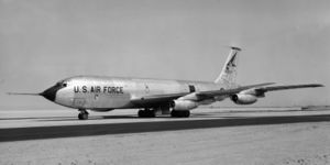
On 1 October 1958, the National Advisory Committee for Aeronautics became the nucleus of the National Air and Space Administration, and the station painters had a field day repainting the logos on our airplanes from NACA to NASA. In the same month, the Air Force asked NASA to study another problem. In this case it was the new KC-135, the USAF tanker version of the Boeing 707 airliner. Some Air Force pilots had found that the new tanker had a tendency to get into an uncontrollable Dutch roll, that had almost ended in disaster a few times. A Dutch roll is an uncoordinated, persisting yawing and rolling motion, and is so named because it resembles the motions of a Dutch skater with his hands folded behind him.
In a susceptible airplane, any small perturbation such as a control pulse or a side wards gust that causes a yawing motion can start the Dutch roll. The yawing motion will push one wing forward faster than the other, the wing will produce lift and roll upward, and at the same time produce more drag than the backward moving wing. The increased drag will then start a yawing moment in the opposite direction, and the process will repeat with the opposite wing now moving forward and gaining lift. The rolling and yawing oscillation then repeats continuously, usually at the same amplitude in each swing. Airplanes having roll stability (dihedral effect) more powerful than directional stability (vertical stabilizer weathervaning effect) seem to be more prone to Dutch roll. A more powerful vertical stabilizer would tend to resist the initial yawing movement. Swept wings also seem to make an aircraft more prone to Dutch roll. In fact the venerable DC-3 has a moderate Dutch rolling tendency brought about by the swept leading edge of the wings. [8, pp.49-52]
Dutch roll will normally continue ad infinitum, and will remain at the same amplitude, but can be annoying and uncomfortable to passengers. The real problem arises when pilots try to correct it; even seasoned pilots. The oscillation is a tradeoff between rolling and yawing where the roll is in one direction, and the yaw is in the opposite direction. That is, right roll accompanied by left yaw for instance. This motion can be non-intuitive to pilots, and most pilot attempts at correction have actually fed more energy into the oscillation with rapidly diverging results up to the point of losing control. The best approach for a pilot, unless specially trained, is to keep the controls neutral. Today, production aircraft that were initially subject to Dutch roll have been given aerodynamic modifications and stability augmentation systems to alleviate the condition. The task to the High Speed Flight Station was to determine just what those changes should be for the KC-135, and thus also for the forthcoming Boeing 707 airliner.
Stability and control specialist Ed Holleman was to lead the investigation, and I was assigned to assist him. Our first job was to program the station’s general purpose analog flight simulator to replicate the dynamics of the KC-135. Next we took turns flying the simulator while trying to tame the oscillations, and in so doing I, in particular, had many crashes. We soon learned that any attempt to fight the amplitude of the roll made it worse. We found, instead that the pilot had to oppose the velocity of the roll and had to be in effect human yaw and roll dampers. This led to the very non intuitive control motion of trying to hold the plane at maximum bank angle as it started to roll toward the other side. Then you had to resist the rolling velocity until the plane reached maximum bank angle in the opposite direction. Only then did you reverse the yoke and try to hold the airplane in the bank. After a few cycles of such control motions, the Dutch roll damped right out.
The KC-135 was equipped with a yaw damper that we had programmed into our simulator, and had set at the gain used in the actual airplane. Next we tried setting the yaw damper gain much higher, and found it very helpful in combating Dutch roll. Now that we thought our simulation was representative of KC-135 dynamics, and that we had manual and automatic means of taming the oscillations, we asked our station test pilots to fly the simulator. We started them with the basic airplane without yaw damper, and asked them to try to control the oscillations, without telling them our findings. The result was usually a wildly diverging oscillation, except for one the four pilots, Stanley Butchart, who had an uncanny ability to correct the oscillation. We asked Stan what he did, but he said he was not sure. He said he just did what ever he had to do. We watched him carefully and recorded his control motions, and found that he was subconsciously using our findings of opposing the roll velocity, rather than the amplitude. We briefed the other pilots on the technique, and they were soon controlling the oscillations. We next ran a series of tests with the pilots using the recovery technique at different yaw damper setting's. Then we were ready for the next stage, flight tests.
The Air Force loaned a KC-135 to the High Speed Flight Station, and the Instrumentation Division readied it for flight testing. In this case there was no problem finding room for the instrumentation package in the huge airplane. Because the performance of the yaw damper was going to be central to the flight study, the instrumentation engineers had to find a way to carefully calibrate the output of the planes yaw rate sensing gyro with real yaw rates and with the amount of rudder deflection caused by a given amount of yaw rate. They came up with a most rapid and ingenious solution. In stead of devising some sort of expensive controllable tilt table, they simply removed the gyro from the plane, still connected to the stability augmentation system in the plane with long wires, and hung the gyro on a pendulum along with a master instrumentation gyro. By simply letting the pendulum swing they could produce and record sensor outputs from both gyros as well as simultaneously recording the resultant rudder deflections at various gain settings.
Our flight test report was to cover three areas: effectiveness of the yaw damper in combating Dutch roll at different gain settings, effectiveness of our pilot recovery technique, and recommended aerodynamic modifications such as enlarged vertical stabilizer & predicted effectiveness. My job in the flight testing process was to man the stability augmentation system, make yaw damper gain changes according to the test plan, and record the settings. Then came the first day of flight testing. I was issued a parachute, and the crew chief showed me how to open a door near my station. He told me if I had to abandon ship, I should dive head first out of the door that was about a foot above the wing. He said the air stream would carry me off, and I would never hit the wing. When I saw the horizontal stabilizer pass overhead, I should pull the rip cord. The yaw damper testing went rapidly, and it took only a few days to get data in all flight conditions. Then came the recovery techniques.
Our two test pilots, Stan Butchart and Jack McKay were to try the recovery technique at a number of yaw damper settings and flight conditions, all of which would be recorded for later analysis. First we would make runs with positive damper settings, meaning the damper was augmenting the plane’s natural yaw damping. This took a few days of mild rolling back and forth. Then came the fun part. The plan next called for perfecting the recovery technique with the yaw damper reversed, meaning the damper would be making the Dutch roll tendency worse. My job was to make the yaw damper settings. If I got a call from the cockpit to “reverse the damper” I was to to immediately set it to a high positive value because the pilots were losing control. Also, if I sensed that the plane was going out of control, whether there was a call from the cockpit or not, I was to reverse the yaw damper on my own. The criteria was if we rolled more than 45 degrees. We started the tests, and it was like being back on the destroyer in a heavy sea. I got a number of calls from the cockpit, “reverse the damper! reverse the damper!,” but never had to take action on my own. As time went on, you could tell that Stan and Jack were getting better at the maneuver.
The test pilots were finally confident they could handle just about any manner of Dutch roll, so we were free to go back to our desks to analyze data and write the report to the Air Force. We also recommended heightening the vertical stabilizer and/or adding a ventral fin to give the plane more natural directional static stability and damping. This was eventually done with ventral fin on some models and higher stabilizer on others. There is one tragic sequel. On 19 October 1959, during a customer acceptance flight Boeing pilots demonstrated a new 707 to Braniff Airways pilots. As part of the process, the Boeing pilot was to turn off the yaw damper and instruct the customer pilots in Dutch roll recovery. The customer pilot’s attempt at recovery was quick but in the wrong direction, and the craft started a Dutch roll oscillation that the Boeing pilot could not overcome. The plane rolled completely over, and threw off three engines, changing the center of gravity so much that it was no longer flyable. The plane crashed in a river bed near Arlington, Washington, killing four of the eight on board. The incident made me really appreciate Stan Butchart’s and Jack McKay’s flying skill.
