File:Ohio Insulator Outdoor Test Lab 1929.JPG: Difference between revisions
(This shows the 1929 Ohio Insulator high-voltage test lab on the estate of A. O. Austin (chief engineer of the Ohio Brass Co. and factory manager of the Ohio Insulator Factory in Barberton, Ohio). At this time, the Ohio Insulator Co. was a division of the) |
(-> Creation failed: Unsupported filetype!) |
||
| Line 1: | Line 1: | ||
This shows the 1929 Ohio Insulator high-voltage test lab on the estate of A. O. Austin (chief engineer of the Ohio Brass Co. and factory manager of the Ohio Insulator Factory in Barberton, Ohio). At this time, the Ohio Insulator Co. was a division of the Ohio Brass Co. whose headquarters were in Mansfield, Ohio. The central estate of the late O. C. Barber (founder of Barberton, OH) including a mansion and the horse barn shown was purchased by A. O. Austin in 1926. The three test transformers shown mounted on porcelain tile piers are rated 750 kv 500 kva each. The transformers were manufactured by Allis-Chalmers and installed sometime prior to 1929. | This shows the 1929 Ohio Insulator high-voltage test lab on the estate of A. O. Austin (chief engineer of the Ohio Brass Co. and factory manager of the Ohio Insulator Factory in Barberton, Ohio). At this time, the Ohio Insulator Co. was a division of the Ohio Brass Co. whose headquarters were in Mansfield, Ohio. The central estate of the late O. C. Barber (founder of Barberton, OH) including a mansion and the horse barn shown was purchased by A. O. Austin in 1926. The three test transformers shown mounted on porcelain tile piers are rated 750 kv 500 kva each. The transformers were manufactured by Allis-Chalmers and installed sometime prior to 1929. | ||
The transformers were used to charge the wire-cage conductor which served as the high-voltage electrode of a large capacitor. A buried ground plane served as the other electrode. An impedance in the transformer primary was shorted generating an over-voltage which caused the sphere gap to flashover. The sphere gap on the right is connected to the wire cage conductor and has a smaller gap than the spheres on the left. A water hose resistor is shown connected from the lower right sphere to ground. This maintains the lower sphere potential near ground prior to sparkover and provides a bleeder resistor to shape the decay of the tail of the impulse voltage wave. | The transformers were used to charge the wire-cage conductor which served as the high-voltage electrode of a large capacitor. A buried ground plane served as the other electrode. An impedance in the transformer primary was shorted, generating an over-voltage which caused the sphere gap to flashover. The sphere gap on the right is connected to the wire cage conductor and has a smaller gap than the spheres on the left. A water hose resistor is shown connected from the lower right sphere to ground. This maintains the lower sphere potential near ground prior to sparkover and provides a bleeder resistor to shape the decay of the tail of the impulse voltage wave. | ||
Full scale transmission towers were tested as shown in the background. The highest AC transmission line voltage was 220 kv at this time. High-voltage test insulator configurations located on the right, not shown in the photo, could also be tested. | Full scale transmission towers were tested as shown in the background. The highest AC transmission line voltage was 220 kv at this time. High-voltage test insulator configurations located on the right, not shown in the photo, could also be tested. | ||
Latest revision as of 16:44, 28 May 2014
This shows the 1929 Ohio Insulator high-voltage test lab on the estate of A. O. Austin (chief engineer of the Ohio Brass Co. and factory manager of the Ohio Insulator Factory in Barberton, Ohio). At this time, the Ohio Insulator Co. was a division of the Ohio Brass Co. whose headquarters were in Mansfield, Ohio. The central estate of the late O. C. Barber (founder of Barberton, OH) including a mansion and the horse barn shown was purchased by A. O. Austin in 1926. The three test transformers shown mounted on porcelain tile piers are rated 750 kv 500 kva each. The transformers were manufactured by Allis-Chalmers and installed sometime prior to 1929. The transformers were used to charge the wire-cage conductor which served as the high-voltage electrode of a large capacitor. A buried ground plane served as the other electrode. An impedance in the transformer primary was shorted, generating an over-voltage which caused the sphere gap to flashover. The sphere gap on the right is connected to the wire cage conductor and has a smaller gap than the spheres on the left. A water hose resistor is shown connected from the lower right sphere to ground. This maintains the lower sphere potential near ground prior to sparkover and provides a bleeder resistor to shape the decay of the tail of the impulse voltage wave. Full scale transmission towers were tested as shown in the background. The highest AC transmission line voltage was 220 kv at this time. High-voltage test insulator configurations located on the right, not shown in the photo, could also be tested.
File history
Click on a date/time to view the file as it appeared at that time.
| Date/Time | Thumbnail | Dimensions | User | Comment | |
|---|---|---|---|---|---|
| current | 20:41, 27 May 2014 | 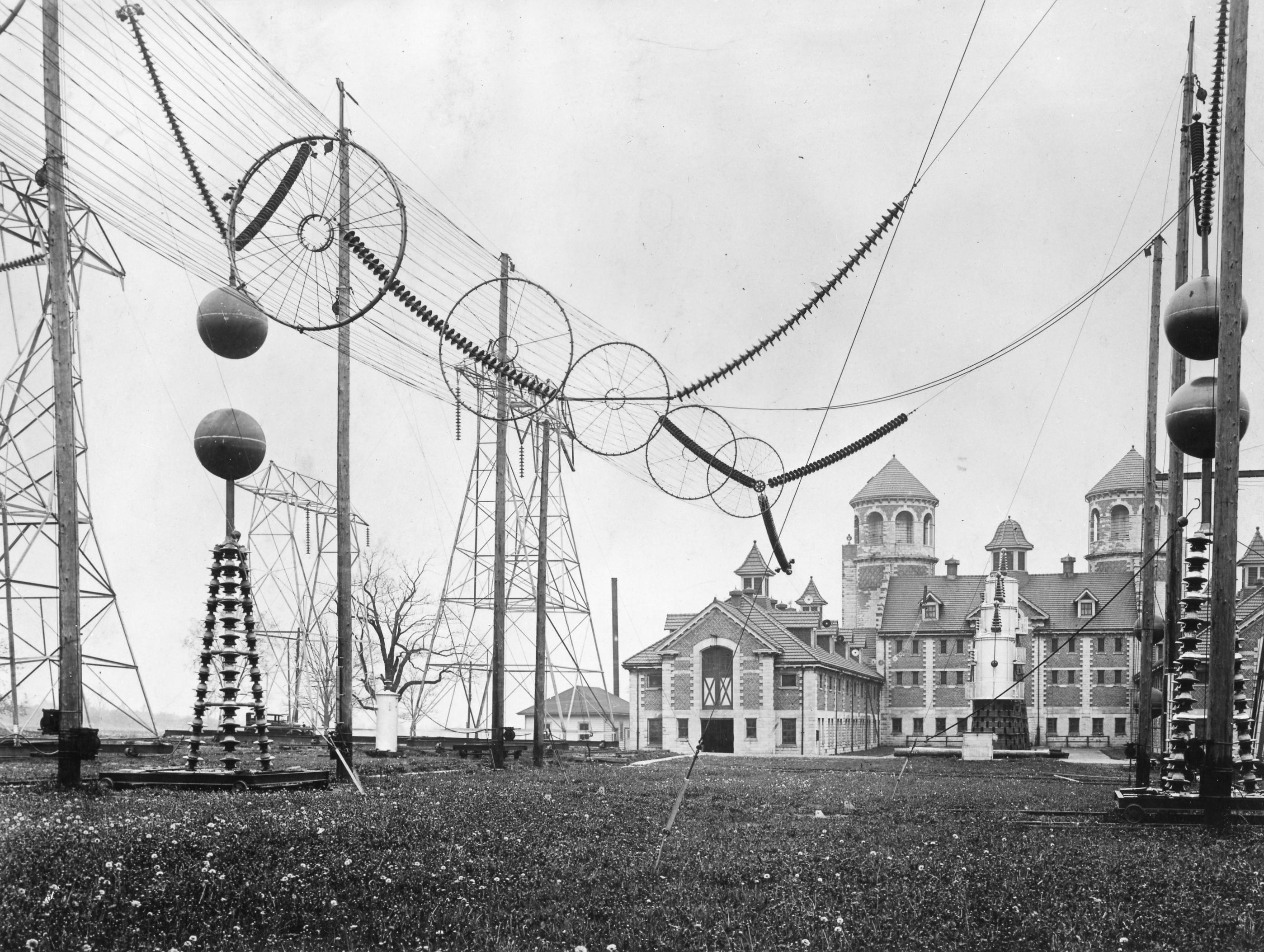 | 2,796 × 2,106 (838 KB) | Mstehney (talk | contribs) | This shows the 1929 Ohio Insulator high-voltage test lab on the estate of A. O. Austin (chief engineer of the Ohio Brass Co. and factory manager of the Ohio Insulator Factory in Barberton, Ohio). At this time, the Ohio Insulator Co. was a division of the |
You cannot overwrite this file.
File usage
The following page uses this file: