File:Ohio Brass 750 kv Test Transformers.JPG: Difference between revisions
(This photo has a caption prepared by the Advertising Department. An oil tank and high-voltage bushing are shown on the left. The sphere gap mounted on top of the bushing is clearly shown. Three 750 kv test transformers are shown in the bay of the "ornat) |
(-> Creation failed: Unsupported filetype!) |
||
| Line 1: | Line 1: | ||
This photo has a caption prepared by the Advertising Department. An oil tank and high-voltage bushing are shown on the left. The sphere gap mounted on top of the bushing is clearly shown. | This photo has a caption prepared by the Advertising Department. An oil tank and high-voltage bushing are shown on the left. The sphere gap mounted on top of the bushing is clearly shown. | ||
Three 750 kv test transformers are shown in the bay of the "ornate horse barn." This barn was built by O. C. Barber (founder of the town of Barberton, Ohio) sometime around 1910 as part of his several thousand acre estate. A. O. Austin (chief engineer of the Ohio Brass Co. and factory manager of The Ohio Insulator Plant) bought O. C. Barber's mansion and horse barn and approximately 400 surrounding acres in 1926. O. C. Barber had passed away in 1920. | Three 750 kv test transformers are shown in the bay of the "ornate horse barn." This barn was built by O. C. Barber (founder of the town of Barberton, Ohio) sometime around 1910 as part of his several thousand acre estate. A. O. Austin (chief engineer of the Ohio Brass Co. and factory manager of The Ohio Insulator Plant) bought O. C. Barber's mansion and horse barn and approximately 400 surrounding acres in 1926. O. C. Barber had passed away in 1920. | ||
The three test transformers were used to charge the wire cage conductor which served as one plate of a large capacitor. This conductor is shown suspended by V strings of insulators attached to wood poles on both sides of the conductor. | The three test transformers were used to charge the wire cage conductor which served as one plate of a large capacitor. This conductor is shown suspended by V strings of insulators attached to wood poles on both sides of the conductor. A conductor mesh buried below ground served as the ground plate of the capacitor. The right (east) and left (west) large sphere gaps were adjustable. The copper spheres were 150 cm (about 60 in.) in diameter and were made by electroplating. The left sphere gap could be used to apply impulse voltage to test specimens on the right side. | ||
A synchronous switch was used to produce either a positive or negative transient over-voltage to spark over the sphere gap and apply the capacitor voltage to the test specimen. Note the lower spheres of each gap are insulated by a three column (tripod) pier of switch insulators. Part of the synchronous switch circuit was used to trigger the "Dufuor" oscillograph that, along with a suitable high voltage divider, recorded the test voltage. | A synchronous switch was used to produce either a positive or negative transient over-voltage to spark over the sphere gap and apply the capacitor voltage to the test specimen. Note the lower spheres of each gap are insulated by a three column (tripod) pier of switch insulators. Part of the synchronous switch circuit was used to trigger the "Dufuor" oscillograph that, along with a suitable high voltage divider, recorded the test voltage. | ||
The smaller building shown to the left and in the background is the "colt barn." The colt barn has been restored and is now the home of the Barberton Historical Society. All three transformers had been removed from the bay of the horse barn before it was destroyed by fire around 1967. The location of the horse barn and the outdoor test lab is now occupied by upscale residential housing bisected by "Austin Drive." A. O. Austin requested in 1956 that the mansion and the surrounding acres be annexed by the City of Barberton. Following failed efforts to form a foundation to preserve the mansion, it was razed to make room for a shopping complex and residential housing. A. O. Austin passed away in 1964. | The smaller building shown to the left and in the background is the "colt barn." The colt barn has been restored and is now the home of the Barberton Historical Society. All three transformers had been removed from the bay of the horse barn before it was destroyed by fire around 1967. The location of the horse barn and the outdoor test lab is now occupied by upscale residential housing bisected by "Austin Drive." A. O. Austin requested in 1956 that the mansion and the surrounding acres be annexed by the City of Barberton. Following failed efforts to form a foundation to preserve the mansion, it was razed to make room for a shopping complex and residential housing. A. O. Austin passed away in 1964. | ||
Latest revision as of 16:42, 28 May 2014
This photo has a caption prepared by the Advertising Department. An oil tank and high-voltage bushing are shown on the left. The sphere gap mounted on top of the bushing is clearly shown. Three 750 kv test transformers are shown in the bay of the "ornate horse barn." This barn was built by O. C. Barber (founder of the town of Barberton, Ohio) sometime around 1910 as part of his several thousand acre estate. A. O. Austin (chief engineer of the Ohio Brass Co. and factory manager of The Ohio Insulator Plant) bought O. C. Barber's mansion and horse barn and approximately 400 surrounding acres in 1926. O. C. Barber had passed away in 1920. The three test transformers were used to charge the wire cage conductor which served as one plate of a large capacitor. This conductor is shown suspended by V strings of insulators attached to wood poles on both sides of the conductor. A conductor mesh buried below ground served as the ground plate of the capacitor. The right (east) and left (west) large sphere gaps were adjustable. The copper spheres were 150 cm (about 60 in.) in diameter and were made by electroplating. The left sphere gap could be used to apply impulse voltage to test specimens on the right side. A synchronous switch was used to produce either a positive or negative transient over-voltage to spark over the sphere gap and apply the capacitor voltage to the test specimen. Note the lower spheres of each gap are insulated by a three column (tripod) pier of switch insulators. Part of the synchronous switch circuit was used to trigger the "Dufuor" oscillograph that, along with a suitable high voltage divider, recorded the test voltage. The smaller building shown to the left and in the background is the "colt barn." The colt barn has been restored and is now the home of the Barberton Historical Society. All three transformers had been removed from the bay of the horse barn before it was destroyed by fire around 1967. The location of the horse barn and the outdoor test lab is now occupied by upscale residential housing bisected by "Austin Drive." A. O. Austin requested in 1956 that the mansion and the surrounding acres be annexed by the City of Barberton. Following failed efforts to form a foundation to preserve the mansion, it was razed to make room for a shopping complex and residential housing. A. O. Austin passed away in 1964.
File history
Click on a date/time to view the file as it appeared at that time.
| Date/Time | Thumbnail | Dimensions | User | Comment | |
|---|---|---|---|---|---|
| current | 19:34, 27 May 2014 | 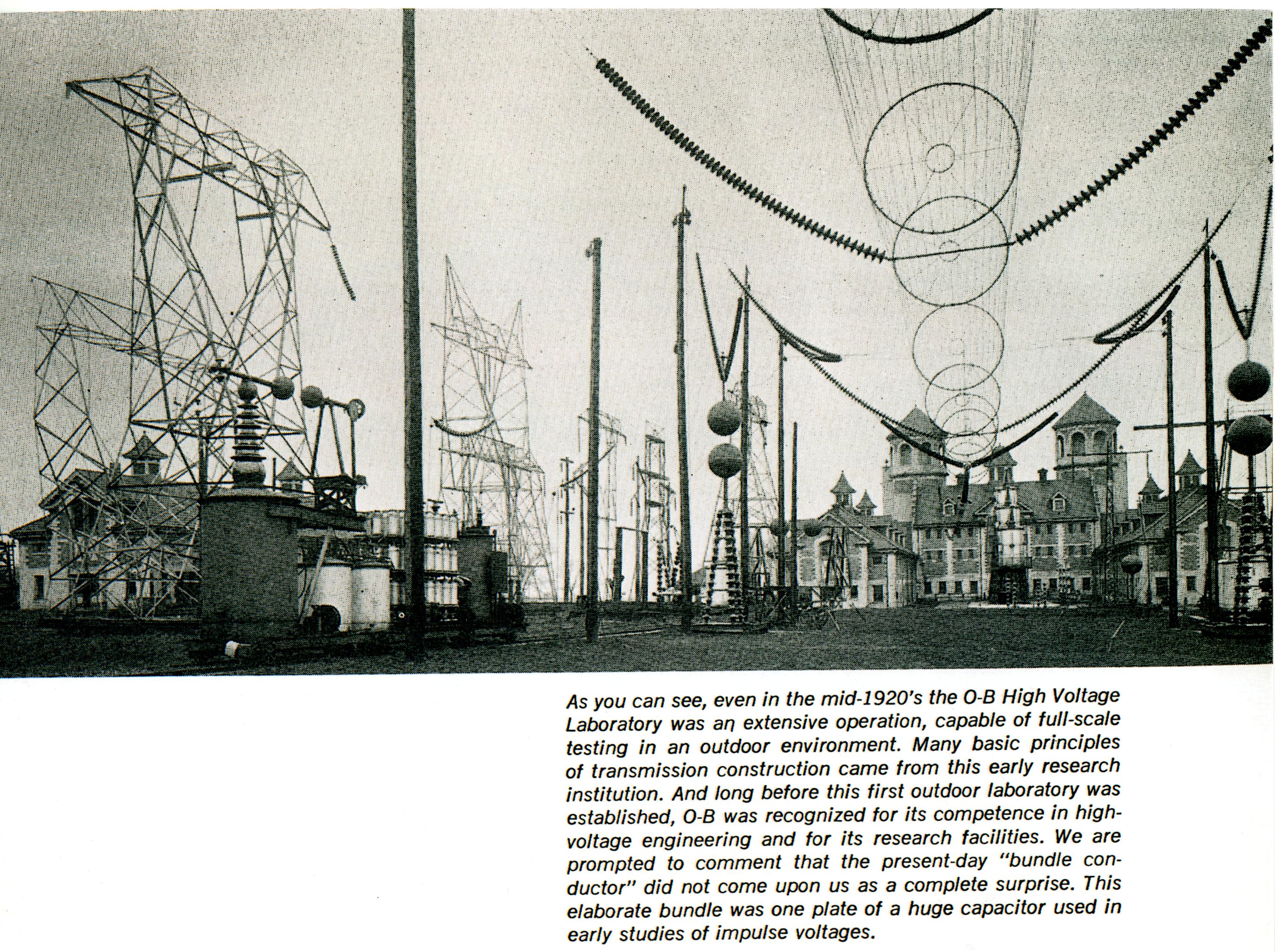 | 2,970 × 2,213 (1.41 MB) | Mstehney (talk | contribs) | This photo has a caption prepared by the Advertising Department. An oil tank and high-voltage bushing are shown on the left. The sphere gap mounted on top of the bushing is clearly shown. Three 750 kv test transformers are shown in the bay of the "ornat |
You cannot overwrite this file.
File usage
The following page uses this file: