First-Hand:The Second Generation X-1s - Chapter 7 of The Experimental Research Airplanes and the Sound Barrier
By David L. Boslaugh, CAPT USN, Retired
Inception of the Second Generation
When the idea of an experimental supersonic research aircraft was conceived in late 1943, initial NACA and Air Force thinking was focused on a goal of Mach 1 for the first airplanes, and following that, a new or modified version to reach speeds possibly as high as Mach 2. With CAPT Yeager’s breaching the sonic barrier on 14 October 1947 they were encouraged to start thinking about a second generation capable of higher speeds, and one month later the Air Force issued a task to Bell Aircraft to start design studies of an advanced research airplane based on the X-1s. They wanted a plane capable of Mach 2.5 and altitudes of more than 90,000 feet. With USAF and NACA approval of the design studies, the Air Force on 2 April 1948 issued a contract to Bell Aircraft Corporation to build four new research airplanes designated and specialized as follows:
- X-1A - dynamic stability and structural air load studies including investigation of stability anomalies encountered in X-1 and D-558-I flights.
- X-1B - same as X-1A mission
- X-1C - armaments research including weapons firing and external ordnance carrying at supersonic speeds.
- X-1D - high speed aerodynamic heating research and testing of rocket reaction control systems for out-of-atmosphere flights.
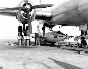
As with the original X-1 series, they would be carried aloft by a heavy bomber, in this case a modified B-50. [39, p.25] [52, p.56, 66]
Design
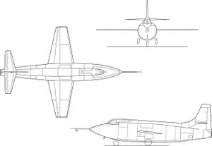
By this time Reaction Motors, Inc. had perfected their propellant turbopump, which conferred two advantages. First, the pump increased rocket engine fuel efficiency, and second, the fuel tanks no longer had to be pressurized to force propellants into the engine. This meant the heavier high pressure propellant tanks with hemispherical ends used in the original X-1s could be replaced by tanks that better fit the form of the fuselage, giving the tanks greater volume, and thus longer rocket burning time. A 37 gallon hydrogen peroxide tank would provide high pressure steam to power the turbopump. Pressurized nitrogen tube bundles would be used to provide source pressure for flap actuators, landing gear extension, and propellant jettison. The fuselages of the new planes would also be extended allowing even more propellant volume. Fuselage extension in this case was dictated by the dimensions of the B-29 mother craft. The nose position of the research airplane would be just aft of the bomber’s front tricycle landing gear wheel well, and the tail position would be limited by the position of the bomber’s after pressure bulkhead. This allowed the fuselage of the new X-1s to be four feet six inches longer than the original X-1s. [19, p p.168-169]
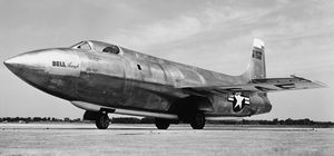
As with the original X-1 series, the second generation would be made of aluminum throughout, and the structure would be designed to withstand plus and minus 18 Gs. Also the cable-connected pilot control systems would remain the same, with the exception of using a control stick rather than the control yoke of the original planes. It had been found that roll control forces in the worst X-1 flight conditions did not require the forces of a control yoke, and furthermore, a control stick would be more compatible with the clearance requirements of the planned pilot ejection seat. As another concession to pilot safety, the side door of the original X-1s would be eliminated in favor of an upward opening pilot canopy that would be blown off before firing the ejection seat. The canopy would also have a projecting windshields to front and sides to give the pilot improved visibility, and the cockpit would be pressurized. The new craft would also use the same eight percent thickness-to-chord ratio airfoil wing as the X-1s, and would use the same XLR11 rocket engine. As a practical matter, much had also been learned about the maintenance features of experimental rocket planes, and the new design would feature a number of maintainability simplification features including more fuselage inspection plate openings. In April 1949, Bell Aircraft completed a full scale mockup of the new design which was subsequently approved by Air Force and NACA inspectors, who authorized start of construction. [19, p.29, 169] [39, pp.25-29]
The X-1C
By 1949, operational military jet fighters, such as the Air Force’s North American F-86 Sabre were capable of reaching Mach 1 in a shallow dive. The X-1C was intended to test ordnance firing, and the carrying of external weapons stores at transonic and low supersonic speeds, so in the interest of economy the USAF elected to cancel the X-1C project in favor of transferring ordnance testing to an operational high performance fighter. Bell only ever built a full scale mockup of the plane to experiment with internal gun placement. [39, p.25, 28]
The Fate of the X-1D
The X-1D was intended for aerodynamic heating research, which was high on the USAF and NACA agenda, and was therefore given production priority over the other second generation planes, and would be the first delivered. When it came to cross-country transportation, the X-1 series had a considerable advantage over other airplanes, they would simply be picked up and carried by their mother planes, so it came to pass that the X-1D was delivered to Edwards by B-50 in July 1951. On 24 July, Bell test pilot Jean Ziegler made a successful contract qualifying glide flight. On impact with the lake bed the X-1D suffered a broken nose landing gear, an unfortunately routine event with the X-1 family, and was not ready again for flight until mid August. The next flight was to be a powered flight under the pilotage of USAF LCOL Frank Everest on 22 August. [19, p.170]
Once aloft and climbing for launch altitude, LCOL Everest entered the X-1D cockpit to check the instruments, and noted that the nitrogen pressure used to actuate flaps, lower the landing gear, and jettison propellants was low. After Everest conferred with the Bell engineers on board, a decision was made to jettison the propellants and abort the flight. Everest reentered the research plane’s cockpit and began pressurizing the liquid oxygen tank for jettison. As tank pressure rose, LCOL Everest momentarily closed the pressurization valve to check oxygen tank pressure. When he opened the valve again, the X-1D was shaken by an explosion somewhere in its insides. Simultaneously, a nearby chase plane pilot reported smoke and flames coming from the stricken plane, and the B-50 crew saw smoke billowing up into the mother plane’s fuselage. Fortunately, because of the X-1Ds upward opening canopy design, Everest was able to make a quick egress from the cockpit, and as soon as he was clear, flight engineer MAJ Jack Ridley pulled the launch handle to free the craft. A few minutes later, the plane was destroyed when it hit the desert floor in a remote area of Edwards AFB. The X-1D had not made even one research flight. [19, pp.170-171]
An accident review board is always convened to try to find the cause of a military aircraft accident. In this case the board determined that the “most probable cause” was leaking alcohol vapor from the main fuel tank, that had been ignited by an electrical spark. The coincidence of the explosion occurring at the same instant that Everest opened the oxygen tank pressurization valve was apparently discounted, most probably because Liquid oxygen, by itself, can not explode. Less than three months later on 9 November 1951, as already has been related, the X-1-3 would also be destroyed in an explosion. [52, p.66] [39, p.28]
The X-1A
Dynamic Stability and Control Investigations
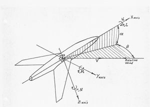
There are two categories of airplane stability. The first is called static stability, and can be determined quite well by wind tunnel studies on models before the real airplane flies. Directional static stability relates to the tendency of the craft to realign itself with the air stream when it yaws (turns) right or left with respect to the airflow, and longitudinal static stability is the tendency of the plane to realign with the air stream when disturbed in pitch (angle of attack). Both of these measures are provided primarily by the weathervane effect of the horizontal and vertical stabilizers in realigning the plane with the air stream when disturbed in flight. Lateral static stability is the tendency of an aircraft to right itself in roll when the plane sideslips. Wing dihedral is usually the main determinant of lateral static stability.
Dynamic stability relates to the motions of an airplane when disturbed in roll, pitch, or yaw, and has a lot to do with how rapidly an oscillation about one of these axes is damped out, that is, how much it “hunts” before settling down. In a light plane, or even an airliner the oscillations about an axis when the plane is disturbed in flight seem to be non existent or hardly even felt. Such a craft is said to be well damped. High performance airplanes such as fighter airplanes, however, can be another story with a tendency to make a number of oscillations when disturbed in flight. In some circumstances the oscillations can build up with disastrous results, and they are sometimes caused by pilot’s attempts at control that actually feed the oscillations. With the experimental research airplanes proceeding into flight regions never before explored, there would be many surprises and much to learn about dynamic stability in high speed and high altitude flight.
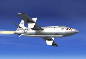
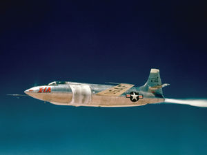
The mission of the X-1A was to gather dynamic stability and control data at high mach numbers (up to mach 2.5 if possible) and at altitudes up to 90,000 feet. The new craft was delivered from Bell’s Buffalo, NY, plant by B-50 express on 7 January 1953, and Bell pilot Jean Ziegler made glide flights on 14, and 20 February. He then made four powered flights, getting up to Mach 0.93 on his last flight on 25 April. Following that, the X-1A was returned to Buffalo to correct some problems found in Ziegler’s flights and to replace the pressurized nitrogen canisters with spherical tanks as a result of the findings of the X-1-3 explosion in November 1951. The craft was back at Edwards by mid November, and on 21 November Chuck Yeager made the First Air Force speed flight to Mach 1.51. Yeager’s next flight was on 2 December to Mach 1.5, during which he reported the need for very heavy stick forces at that speed. On 8 December Yeager achieved Mach 1.9 in a slight climb to 60,000 feet. [39, p.28] [52, pp.66-67]
Roll Coupling
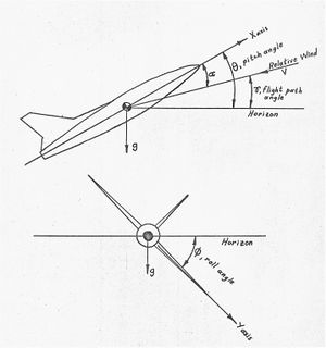
From side-to-side an airplane is symmetrical (usually) but from top to bottom an aircraft is asymmetrical because of the vertical tail sticking up above the airplane. When an aircraft rolls, the centrifugal force of the roll will want to pull the tail out of line with the air stream and try to make the longitudinal axis of the plane rotate about the axis of the roll, that is to pull the fuselage out at a right angle to the air stream. This phenomenon is called inertial coupling, or more commonly, roll coupling. Another factor that can cause roll coupling is the rolling of an aircraft when the fuselage is out of line with the air stream in pitch or yaw. In this case the axis of the roll will usually be in line with the air stream, with the result that the ends of the fuselage are displaced from the roll axis, and will be effected by centrifugal force tending to pull the fuselage at right angles to the relative wind. Not a good way to fly. These destabilizing forces are relatively weak , and in normal flight the static stabilizing forces of the tail surfaces keeping the plane in line with the air stream far overpower the roll coupling forces. But, if for some reason, the stabilizing forces are small compared to the roll coupling destabilizing forces, there can be drastic consequences. [8, p.53-56]
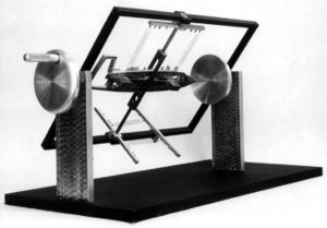
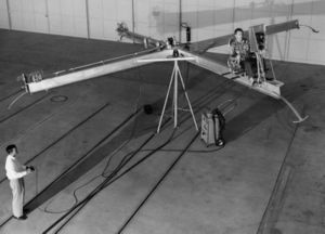
High Speed Flight Station engineer Richard E. Day devised a mechanical model to demonstrate the dynamics of roll coupling. The fuselage is mounted in gimbals that allow it to rotate in pitch and yaw against the restraining springs - that represent the weathervane stabilizing forces of the tail surfaces. One can see that if the crank is turned, centrifugal force on the asymmetrical vertical tail will try to pull the tail toward the outside of the spinning motion If the springs are strong, representing good pitch and directional static stability, centrifugal force will have negligible effect in displacing the fuselage. But if the springs are weak, representing the weak static stability of some aircraft at high Mach numbers, the fuselage will be appreciably displaced. One can also appreciate that the mass and spring combination of the fuselage will want to vibrate back and forth once pulled out of line, and will oscillate a number of cycles before damping down. To make matters worse, if the period of a rolling oscillation is about the same as either the natural period of vibration in pitch or yaw, energy will be fed from the rolling motion into the resonant pitching or yawing vibration, with disastrous results. NACA photo
Chuck Yeager’s next flight in the X-1A was to be an all out attempt to achieve Mach 2.5, and NACA engineers had already done extensive wind tunnel tests of second generation models at those speeds. What they found was the X-1A could be expected to have almost no directional static stability at speeds above Mach 2.3, and very little longitudinal static stability. The main reason for the loss of stability was wing shock waves that, at this speed, would impinge on the tail surfaces, and in conjunction with interacting with shock waves from the tail surfaces, would negate the surface’s stabilizing effectiveness. Engineers cautioned Yeager not to make any abrupt control inputs at these speeds, for they were not at all sure what the airplane would do.
Chuck Yeager’s Wild Ride
On 12 December 1953, Yeager made his drop at 30,500 feet and lit three XLR11 chambers as soon as he was clear of the B-29. Climbing to 45,000 feet he lit his fourth chamber and proceeded to 76,000 feet where he leveled off. He quickly exceeded Mach 2, and as he was reaching Mach 2.4, the X-1A began yawing and rolling to the left. Yeager’s attempt to correct the motions with right aileron and rudder resulted in a violent right roll, and every indication that he was no longer in control. Yeager shut the rocket motor off at Mach 2.44 as the craft began a violent rolling and summersaulting tumble that finally developed into an inverted flat spin at 29,000 feet. It took him another 4,000 feet to recover from the spin and then start a glide back to the dry lake bed. Chuck Yeager had met the roll coupling monster and survived. [19, pp.181-182]
Yeager was so knocked around in the cockpit that he had not only lost consciousness for a while, but also his helmet had hit the inner canopy liner so hard that it broke the liner. The X-1A did not yet have an ejection seat, and Yeager radioed on the way down that if he would have had an ejection seat, he would have used it. Upon landing, the only other X-1A damage were the bent external angle of attack and yaw measuring vanes. Thorough inspection showed no structural damage. The decision to build the research airplanes to withstand 18 Gs had paid off. Yeager noted in his flight comment sheet, “I Don’t Think You’ll Have to Run a Structure Demonstration on this Damned Thing!” Mach 2.44 would mark the highest speed achieved in any of the X-1 series, and it would be Yeager’s last flight in an X-1. The Air Force and NACA decided that the remaining X-1s would be limited to Mach 2. As a result of knowledge gained in the flights of the X-1s and other high speed research airplanes, aircraft designed to exceed Mach 2 are now fitted with very large vertical tail surfaces, and often with double vertical stabilizers and/or ventral fin stabilizers to give them sufficient high speed directional stability. The reader will recall that NACA pilot Scott Crossfield, on 20 November 1953, became the first man to exceed twice the speed of sound with a new record of Mach 2.005 in the Douglas D-558-II No. 2. Thanks to Yeager’s wild ride, Scotty only held that record for 22 days. [19, p.182]
The next phase of Air Force testing was to explore the X-1A altitude capability, to be flown by Major Arthur Murray. He would make 14 high altitude attempts, of which three would successively set new unofficial records. On some of these flights he also experienced severe roll coupling and subsequent out of control tumbles. On 26 August 1954 Murray set a record of 90,440 feet that would last until September 1956 when CAPT Ivan Kincheloe set a new record of 125,907 feet in the Bell X-2. More about this later. In september 1954, the X-1A was turned over to NACA who had it carried back to the Bell plant for modifications including an ejection seat in acknowledgment of the dangers of speeds around Mach 2. [52, pp.66-67] [39, pp.26-29]
The End of the X-1A
The X-1A was ferried back to the NACA High Speed Flight Station in mid 1955, who by then was occupying new office building, hangars, and shops on the edge of the dry lake bed. The next phase of testing was to be detailed dynamic stability and control research at speeds up to Mach 2, and the project would be flown by NACA pilot Joe Walker. Walker made his first flight on 20 July 1955, and gathered data up to a speed of Mach 1.45 and 45,000 feet altitude. His next flight was on 8 August, and Walker lowered himself into the research airplane’s cockpit at 8000 feet while the B-29 was climbing to launch altitude. At one minute before drop, while Walker was making preparations for release, an explosion rocked the X-1A. This time it was clear that the liquid oxygen tank had exploded because one of the chase pilots could see the liquid oxygen draining out. Crew members quickly opened the stricken plane’s canopy and helped Walker out. Crew chief Richard Payne then tried to jettison the alcohol fuel, but very little came out. The X-1A was not only on fire but also extremely tail heavy because of the full alcohol tank in the aft fuselage. There was a strong possibility that if the plane was released, its nose would pitch right up into the mother plane’s fuselage. The B-29 was piloted by NACA test pilot Stanley Butchart who decided to make the hardest possible left turn the B-29 could make in order to throw the burning research airplane free when he pulled the release handle. It worked, and witnesses said the X-1A pitched up so sharply it almost made a loop before tumbling down to the Edwards AFB bombing range. [20, pp.133-134
By now, four rocket research airplanes had blown up under their mother planes: the X-1-D on 22 August 1951, the X-1-3 on 9 November 1951, the X-2-2 on 12 May 1953, and the X-1A on 8 August 1955. We have not yet reviewed the advanced X-2 research planes which were to be capable of speeds up to Mach 3, but the second of the craft had blown up even before it was delivered from the factory. It had been on a captive flight under a B-50 mother plane over Lake Ontario near the Bell Aircraft plant, and had blown up while making a propellant jettison test. In this case the explosion was so severe that the X-2 was shattered to pieces which fell into the lake, and only a few shards capable of floating were ever found. Bell pilots were able to land the mother plane, but it was unrepairable. The Bell test pilot Jean Ziegler and one crew member had been killed. Bell Aircraft even went to the extent of building a new X-2 fuselage complete with engine, fuel tanks, and all other equipage in order to run tests that might point the way to the cause of the explosion. The final verdict of the accident review board was probable leaking alcohol vapor ignited by an electrical spark, the same finding as the X-1D explosion. [36, pp.31-34]
The cause of the X-1-3 explosion had been adjudged to possibly have been a brittle super cooled nitrogen tube bundle that exploded. Pieces of the flask had been found more than 100 feet from the scene, and later impact tests on the super cooled, pressurized tubes had led to explosions. In the case of the X-1A, however, the nitrogen flasks had been replaced by spherical tanks, and they were found intact in the wreckage. The nitrogen tanks and tube bundles were eliminated as possible cause. The X-1A wreckage was brought into the HSFS hangar for reconstruction and examination. Later, when Marian and I were working at the High Speed Flight Station we had lunch with NACA engineer Don Bellman who had worked on the accident investigation, and he told us the story of how they finally found the real cause of the four explosions.
Don said that the alcohol fuel tanks had always been the center of suspicion because liquid oxygen, by itself, can not explode. However, the X-1A liquid oxygen tank had clearly been ruptured, and there did not seem to be any culprit that had torn it open from the outside. It looked like there had been an explosion inside the “lox” tank; but what could explode? The Bell X-1B, also in the hangar, was virtually identical to the destroyed ship, and he and a Bell engineer had the X-1B oxygen tank inspection plate opened. Inside, they saw a brown, oily liquid on the bottom of the tank; about a tablespoon full. They scooped up the liquid, and the Bell engineer questioned whether it might be explosive in the presence of liquid oxygen. Don described their next highly sophisticated experiment. They put a drop of the liquid on a bench, and then poured a couple of drops of liquid oxygen over it, and then hit the mixture with a hammer. The result was like a rifle shot; they were definitely on to something.
Chemical analysis showed the brown liquid was a preservative used in leather gaskets in the liquid oxygen system. It had apparently been squeezed out of the gaskets and collected in the tank. They obtained some samples of the gasket material and set up a more formal series of tests, using a stand set up out in a parking lot. They would soak a piece of the gasket in liquid oxygen, and lay it on the stand. Then they would remotely trigger a weight to slide down a rod onto the gasket from varying heights. In 30 drops, they got 30 very satisfying explosions. They found it took hardly any shock to set the material off. The accident review board concluded that just the pressure wave generated by opening the valve to pressurize the oxygen tank for jettisoning was enough initiate explosion. The board agreed the cause of all four explosions had been found. The oxygen system gaskets in all the remaining Bell rocket planes were changed to a different material, and never again was there a propellant tank explosion in the Bell research airplanes. [7, pp.202-203] [19, pp.188-191] [53, p.115]
The X-1B
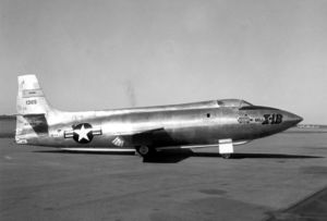
The X-1B had originally been intended for dynamic stability and control research, but with the loss of the X-1D, the X-1B was instrumented for aerodynamic heating research. It was also slated to be fitted later with an experimental reaction control system to gain data for the design of the forthcoming X-15 research airplane’s out-of-the-atmosphere reaction control system. The X-1B arrived at Edwards AFB via B-50 express in June 1954. The Air Force Flight Test Center took possession of the plane and primarily used it in pilot familiarization flights for USAF pilots who would be flying the forthcoming X-2 and X-15 research airplanes. One notable familiarization flight was made on 2 December 1954 by USAF pilot LCOL Frank K. Everest, a designated X-2 pilot. On this flight he achieved Mach 2.3 at 65,000 feet, but when he exceeded Mach 2 he found the craft began an uncontrollable yawing oscillation and rolled 70 degrees from side-to-side, indicating very low lateral and directional static stability at those speeds. The plane was turned over to the NACA High Speed Flight Station the following day with Everest’s warning about the marginal stability characteristics. [7, p.185] [39, pp.27-28]
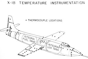
NACA had the X-1B ferried to the Langley Laboratory where, during eight months, instrumentation specialists installed more than 300 thermocouples in the planes skin for aerodynamic heating studies. By August 1955 the plane was back at the High Speed Flight Station, and on 14 August 1956, test pilot Jack McKay made the first of 13 aerodynamic heating flights. His highest speed was Mach 1.94 on 22 May 1957, when a maximum temperature of 185 degrees was recorded at the nose thermocouples. Because of stability problems encountered above Mach 2 in the X-1A, McKay’s flights were limited to Mach 2. McKay’s last heat study flight was on 29 July 1957, and by that time, wing tip extensions had been installed on the craft to accommodate small hydrogen peroxide reaction control system rockets. A new NACA pilot, Neil A. Armstrong would take over the aircraft for the next four flights, making his first familiarization flight on 15 August. Armstrong would then make three flights evaluating the reaction control system to gather design data for the X-15 research airplane’s reaction control system. His last flight was on 23 January 1958, and it would turn out to be the X-1B’s last flight. Following Armstrong’s fourth flight, a routine inspection found cracks in the planes liquid oxygen tank, and attempts at welding the cracks were non productive. In June 1958 NACA decided to retire the X-1B and turn it over to the Air Force Museum at Wright Patterson AFB, Dayton Ohio. The reaction control system was removed and installed in an F-104 “Starfighter”, to be used for training X-15 pilots. [52, p.67] [19, p.191] [39, p.27]
The X-1E
Design
The reader will recall that the X-1-2, was grounded in late 1951 because of fatigue cracks found in the nitrogen spheres used to pressurize the propellant tanks. As a possible replacement, nitrogen spheres removed from the X-1-1 in the Smithsonian were tested but burst under test pressures. In August 1951, the X-1D had blown up, in November 1951 the X-1-3 blew up, and the X-1-1 was in the Smithsonian. By December 1951, there were no remaining X-1s at the High Speed Flight Station, and only two more were on the way, the X-1A and the X-1B; not enough to continue the planned program of flight testing. Other than the nitrogen tanks, the X-1-2 was in good shape, and NACA engineers proposed to give it a new lease on life to alleviate the forthcoming paucity of research airplanes. They calculated that if the plane were equipped with the new Reaction Motors propellant feed turbopump, and given a much thinner wing it would be capable of reaching Mach 2.5. It was proposed that the rebuilding be done in the High Speed Flight Station shops, and in March 1954 the rebuilding project was approved. The rebuilt plane would be given the designation X-1E. [19, p.193]
The proposed new wing was to have a thickness only four percent of the chord; an incredibly thin wing, and a design challenge. The Air Force and NACA contracted with Stanley Aviation Corporation to design and build the new wing. The company had been started by Robert Stanley, a former Bell Aircraft Vice President of Engineering, and Stanley came up with some unique design features to give such a thin wing the stiffness it needed to withstand 18 Gs. As with the other X-1s, the wing’s upper and lower skins were milled out of solid aluminum blanks, and had a root thickness of a half-inch papering to about one 32nd inch at the tips. Different from the original X-1 wings, the new wing would be stiffened by multiple rectangular tapered box spars. The wing would be only 3 and 3/8th inches thick at the root. Design was further complicated by the need to drill 200 pressure measurement orifices and embed 343 strain gages and thermocouples in the wing surfaces. [19, p.193]
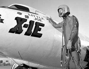
As with the second generation X-1s, the craft would be modified to have an upward opening cockpit canopy with improved visibility, and an ejection seat reused from a retired X-4 research airplane. (The X-4 will be discussed later.) The rocket engine would be a Reaction Motors XLR-8-RM-6 spare left over from the D-558-II Skyrocket project; a higher efficiency version of the X-1’s XLR11 engines. There would be no changes to the original X-1-2 propellant tanks, tail surfaces or landing gear, and only minor changes to the fuselage to accommodate the new cockpit canopy. Fuselage dimensions remained the same, so the X-1E could be carried under the original B-29 mother plane. [39, pp.31-33]
First Flights
By late November 1955, the rebuilt plane had been thoroughly inspected and was ready for flight testing. NACA test pilot Joe Walker made the first glide drop flight on 12 December 1955, and the first powered flight on 15 December. Four flights later, on 7 June 1956, Walker made the first supersonic flight of the X-1E, achieving Mach 1.55, and after three more flights, on 31 August 1956, Walker took the plane out to Mach 2.01. [52, p.68]
Joe Walker’s Belly Slide
Marian and I were married in early March 1957, and moved into our quarters at Edwards Air Force Base soon after. Marian had become accustomed to working for a living, and after a couple weeks of inactivity she had a job at the High Speed Flight Station. On 15 May, I asked if she would like to go up to the station control tower and watch an X-1E drop flight. Joe Walker was scheduled to take the plane out to Mach 2 at 73,00 feet. We listened to the radio conversations and watched the X-1E’s contrail as Walker made his run, achieving both speed and altitude goals. Then we watched the growing dots of the X-1E and two chase planes as they came over the edge of the dry lake; Joe Walker lining up with the runway marked in tar on the lake bed.
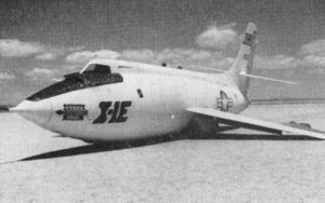
If there is one design feature of the X-1 series that designers might like to do over, it would probably be the size of the elevator. The elevator had sufficient authority at flying speeds to keep the craft well under control, but at landing speed it was not powerful enough to stave off the swift downward reaction of the nose after the main landing gear touched the runway. Many times the nose gear hit hard enough to damage it. Almost every one of the X-1s had damaged nose gear at one time or another as a result of their hitting the runway too hard. We watched as the X-1E touched down on the far end of the runway and simultaneously we heard Joe utter “whoops!” Then we saw a long cloud of dust with the nose of the plane just protruding from the dust, streaking toward the station. After sliding for about a mile, the plane came to rest, and there was silence in the control tower; all anxiously awaiting to hear if the test pilot was OK. Then we heard Walker exclaim over the radio, “Well I’m down.” There was silence in the tower again until my startled, wide eyed bride demanded to know, “Do they always land like that?”
This time, the X-1E’s nose gear had not just been cracked, the main gear as well as the nose gear been wiped off, and there was substantial damage to the underside of the plane. The craft had bounced back into the air when the nose wheel hit and then come down very hard on all landing gear. It would take about four months to repair, and one of our mechanic friends told us that he and another had been dispatched back to the Smithsonian Institution to remove the landing gear from the X-1-1 as no other spare parts were available. The accident review board concluded that a contributing cause of the hard landing was the partial pressure suit and the closed helmet Walker had to wear on this flight because of the planned high altitude. In this case the transparent faceplate of his helmet had distorted his vision on landing.
One of the Few Survivors
We have yet to tell the story of the Mach 3-capable X-2 research airplane that was to take up where the X-1 series left off at Mach 2.5. Unfortunately the X-2 would have an abbreviated research career; meeting destruction in September 1956. With the loss of the X-2 there was thought by Mr. Hubert Drake and other station engineers that with modifications to the X-1E rocket engine and use of an exotic new propellant called Hidyne, having considerably more specific impulse than alcohol, the X-1E could reach speeds near Mach 3. Approval was given to make engine modifications that would allow increasing rocket chamber pressure from 250 to 300 pounds per square inch, and to use the new propellant. On 8 October Joe Walker made what would turn out to be the fastest flight of the X-1E program, Mach 2.24, using alcohol fuel, and with the engine modifications not yet installed. [52, p.68]
In preparation for slowly moving maximum speeds up to Mach 3, and in acknowledgment of the potential danger of stability loss at speeds above Mach 2.3, HSFS engineers designed and fitted two ventral stabilizing fins to the underside of the X-1E fuselage. On 14 May 1958, Walker made an evaluation flight with the new ventral fins, reporting that the fins did improve directional stability, but at the expense of overall maneuverability. Walker would make three more flights in the X-1E and then turn the project over to HSFS test pilot Jack McKay, who made his first familiarization flight on 19 September. McKay would make two more flights with the rocket engine in basic configuration, and then on 16 October he would make the first flight with the increased chamber pressure modifications. Following another flight evaluating the engine modification, on 6 November McKay made his first flight testing the new Hidyne fuel. [19, p.195]
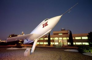
After this flight McKay was fitted with a partial pressure suit to begin higher speed, higher altitude investigations. But upon checking McKay’s fit in the cockpit with pressure suit it was found that with the present ejection seat, parts of the pressure suit would not clear the cockpit upon ejection. The X-1E was temporarily grounded while the the ejection seat was reworked, and inspectors took advantage of the grounding to take routine X-rays of the propellant tanks. What they found was the beginnings of cracks in the tanks, and after 26 flights the X-1E was grounded. NACA officials decided the cost of new tanks was not worth it, in view of the imminent arrival of the Mach 6 capable X-15 research airplane. This ended the X-1E research project. The X-1E is now mounted on a pedestal at the entrance to what was once called the High Speed Flight Station, and now called the Neil A. Armstrong Flight Research Center. It is somewhat ironic that the final survivor of the X-1 research airplane series after 21 years of testing, was the reworked X-1-2, the second airplane to break the sound barrier. [39, pp.31-33] [[19, p.195]
